The following settings are used to define the configuration templates that are applied when a gateway is claimed. Changing these settings in a template does not impact previously claimed gateways unless the template is changed on the device.
More information
Template Name
The template name is selected when applying the template to a gateway.WAN Interface
The WAN setting is only used when the gateway is claimed for the first time from the "Out of Box" state, or after a factory reset. The WAN Interface is ignored if the gateway is claimed again.
| Setting | Description |
|---|---|
| No Change | Use the gateway's default WAN interface configuration, such as the LAN port. |
| Cellular | Enter the Access Point Name (APN) for the SIM cards installed in the device. You can change the APN settings after the gateway is claimed, but changing this setting can cause cellular traffic downtime. Primary APN (SIM 0)—Required. The primary cellular connection for the device. Secondary APN (SIM 1)—Optional, for Dual LTE gateway's only. See supported gateways. A backup connection for more reliable coverage, if necessary. Important! Be sure to enter the correct APN, or the cellular connection will not work. |
Related information
- See Deploy your gateways for detailed instructions.
- See Change the WAN interface to change the WAN setting after the gateway has been claimed.
Ethernet notes
- Select a template with the WAN Interface set to No Change.
- The Ethernet uplink network must support all network requirements.
- Make sure SIM cards are NOT INSTALLED, or a configuration error can occur since the gateway will use whichever interface receives an IP address first.
- Connect the Ethernet cable from the following ports to the network:
- IR1101—port GE 0/0/0
- IR807—port FastEthernet 0
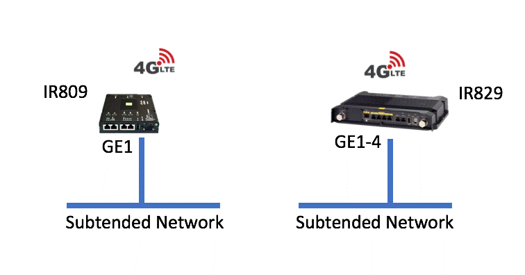
- IR809—port GE0
- IR829—port GE1
Cellular notes:
- Select a template with the WAN Interface set to Cellular.
- The APNs are provided by your wireless carrier. For example, "broadband".
- If using cellular with a private APN, initially connect the gateway over Ethernet so GMM can push the APN config to the gateway. After the config is applied, remove the Ethernet uplink (this is not required if using a public APN).
- See Deploy your gateways for details.
- To install the SIM card, see the following:
- Be sure to use a cellular antenna that provides the best signal and connection. See:
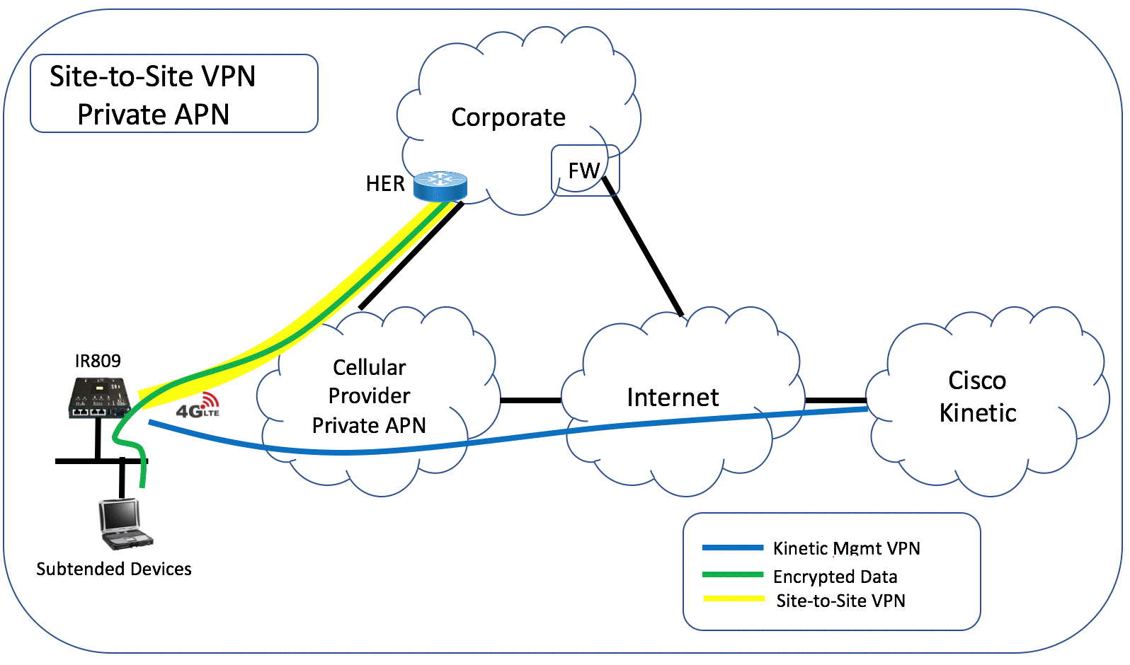
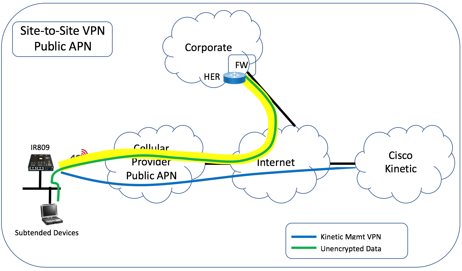
Site-to-site VPN
Enable VPN to create a separate site-to-site connection from the subtended network to your organization’s network. This uses FlexVPN to build a VPN tunnel from the gateway to the Head End Router (HER) at your corporate network or data center.
Below show two customer scenarios for Private APN and Public APN.
Settings
Complete the following to establish the VPN connection. Data from the subtended network will be encrypted across the site-to-site VPN to the corporate network.
| Setting | Description |
|---|---|
| Enabled | Enable your organization's VPN. |
| Router #1 IP Address | The IP address of your organization's headend router. |
| Router #2 IP Address | (Optional) The IP address of your organization's backup headend router. |
| Preshared Key | The preshared key used to authenticate the gateway to your VPN head end router. Each gateway can have its own credential. |
Note: Site-to site VPN connections can optionally use a second backup router, if necessary. If the first router is offline and the second one is used, the second router will continue to be used even when the first one comes back online. If the second server goes offline, then the first server will be used again.
See VPN troubleshooting for more information.
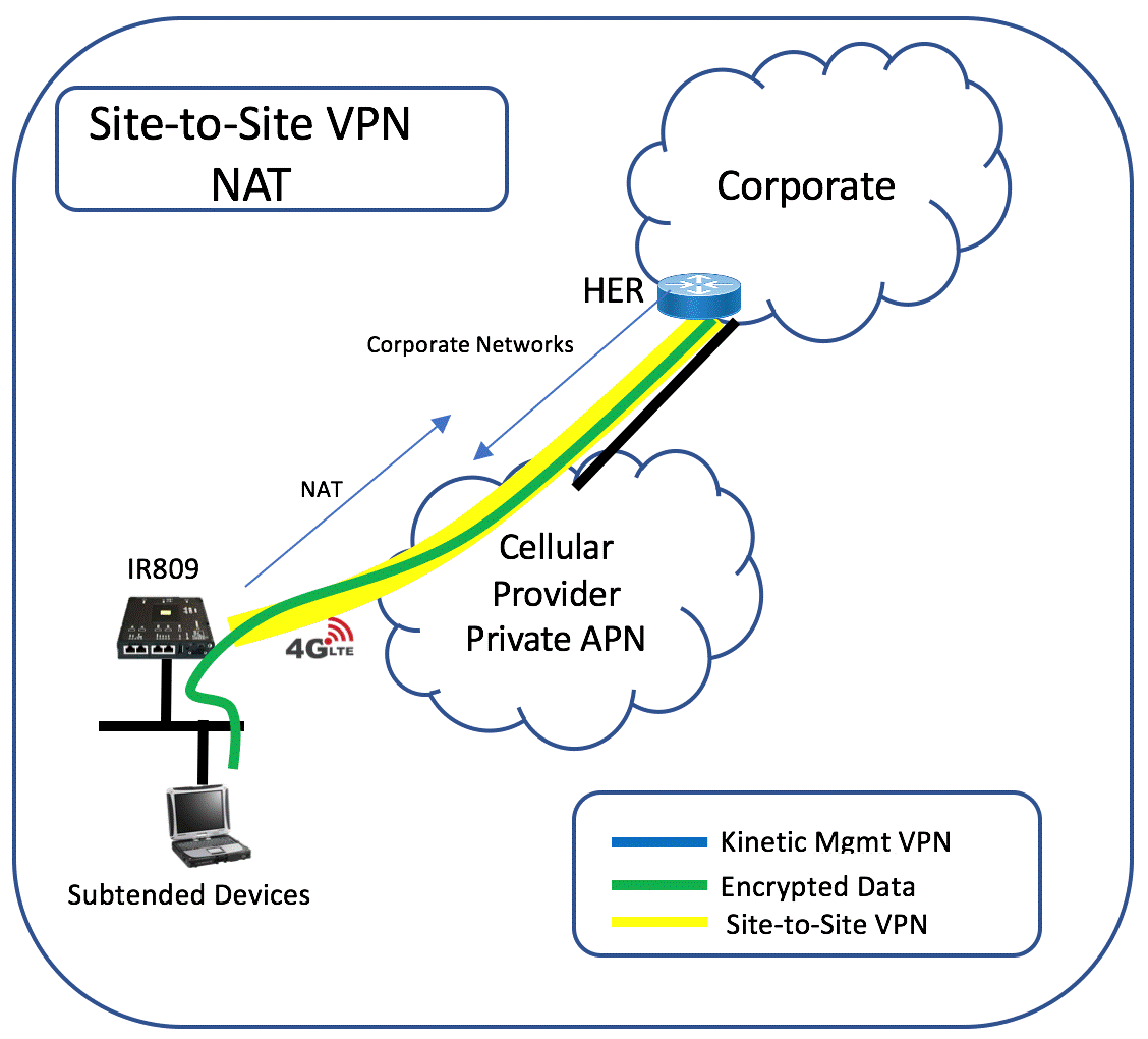
VPN deployment using NAT
Site-to-site VPN can be deployed using NAT for the subtended networks.
NAT for subtended networks uses the Tunnel2 IP address. This is the tunnel IP of the site-to-site VPN on the gateway. The Tunnel2 IP address is part of the FlexSpoke pool use by FlexVPN and is tied to the same network as the loopback IP address of the HER.
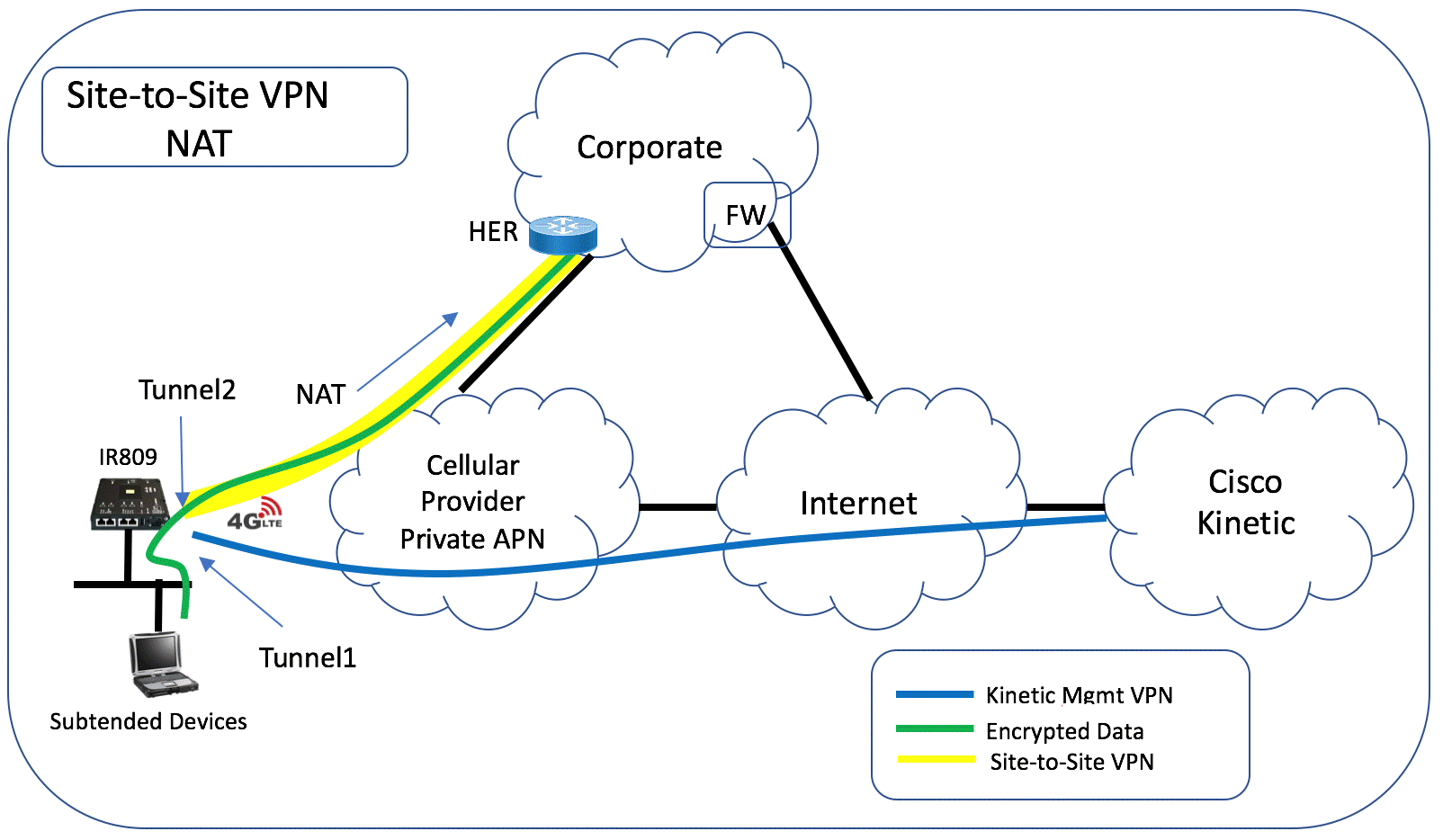
The HER will advertise the networks for the corporate cloud to the gateway using IKEv2. All traffic from the subtended network destined to the corporate cloud will be sent to the Tunnel2 where it is NAT’ed and encrypted by the FlexVPN tunnel. Traffic from the corporate network destined elsewhere will default to the cellular 4G interface and out to the Internet. Note that traffic destined to Cisco GMM is on a separate VRF and will route out of the Tunnel1 interface.
In the NAT scenario, to access the subtended device, either NAT/PAT will be required. NAT/PAT can be configured in the gateway configuration template.
Head End Router (HER) configuration
Site-to-site VPN requires a Head End Router (HER) to be configured that terminates the VPN at the corporate end. The HER is typically a Cisco CSR or ISR. Other gateways that support FlexVPN can also be used.
Configuration requirements
__Gateway configuration__
The gateway specifies the following information:
- The IP address of the head-end router
- The pre-shared-key of the VPN (each gateway can have its own credential)
- (Optional) The identity of the head-end router
Head End Router configuration
The head-end router needs to have the following configuration:
- Crypto ikev2 configurations similar to the one on our cloud CSR
- Individual key-pair for each gateway in the format of GW-SN>@iotspdev.io
- Individual pre-shared-key of each GW pre-programmed
Sample HER configuration
In this example:
- FlexSpoke pool network used is 172.16.4.0/19
- Access-list CLOUD configures the corporate networks to announce to the gateway
- NAT on GE1 (optional)
aaa new-model
!
enable secret <password>
!
aaa authentication login default local
aaa authorization network default local
!
! This is needed to support the primary-secondary VPN feature on the GWs. Also, see corresponding change in "crypto ikev2 profile Flex_IKEv2" section below
crypto ikev2 name-mangler GET_NAME
  email username
!
crypto ikev2 authorization policy default
 pool FlexSpokes
 route set interface
 route set access-list CLOUD
!
crypto ikev2 keyring Flex_key
!
crypto ikev2 profile Flex_IKEv2
 match fvrf any
 match identity remote email domain iotspdev.io

! replace this with the actual identity (e.g. public IP)
 identity local key-id <CSR-Public-IP>
 authentication local pre-share
 authentication remote pre-share
 keyring local Flex_key
 dpd 250 10 on-demand
aaa authorization group psk list default name-mangler GET_NAME
 virtual-template 1
!
interface Loopback100
! Customize as needed for customer network
 ip address 172.16.4.1 255.255.240.0
!
interface GigabitEthernet1
 ip address dhcp
 ip nat outside
 negotiation auto
!
interface Virtual-Template1 type tunnel
 ip unnumbered Loopback100
 ip mtu 1400
 ip nat inside
 ip nhrp network-id 2
 ip nhrp redirect
 ip tcp adjust-mss 1360
 tunnel mode ipsec ipv4
 tunnel path-mtu-discovery
 tunnel protection ipsec profile default
! customize the pool as needed
! You can define a global pool like below
ip local pool FlexSpokes 172.16.4.2 172.16.19.254
! Route exported to gateway
ip access-list standard CLOUD
 permit 192.168.100.0 0.0.0.255
 permit 172.31.0.0 0.0.255.255
! Optional to route Internet traffic through this VPN
 permit any
! Optional NAT config
ip nat inside source list VPN_CLIENTS interface GigabitEthernet1 overload
ip access-list standard VPN_CLIENTS
 permit 172.16.0.0 0.0.31.255
Adding an entry for each gateway at the remote site
Each gateway that is added to the site-to-site VPN needs an entry added for that gateway to the HER.
crypto ikev2 keyring Flex_key
 peer <GW-SN>
  identity email <GW-SN>@iotspdev.io
  pre-shared-key <pre-shared-key>

 ! In addition, if you want to use assign static IP to each GW, define separate authorization policy and pool:

crypto ikev2 authorization policy FTX2053Z09L
   pool <GW-SN>
   route set interface
   route set access-list CLOUD
   no route accept

! Change the IP address as needed
ip local pool <GW-SN>  172.16.4.20
For No-NAT: when full routing is necessary
crypto ikev2 authorization policy default
  pool FlexSpokes
  route set interface
  route set access-list Customer
  route accept all

interface GigabitEthernet1
   no ip nat outside
Subnet Configuration
A Subnet Configuration allows the gateway to provide IP addresses to connected devices from a custom subnet range, instead of the default subnet assigned by the Cisco gateway.
The Subnet Configuration configures the subtended network to a custom configuration that is different than the default. By default, Cisco GMM will configure the /28 subnet for the subtended devices on GE1 (IR809) or GE2-4 (IR829). This subnet is in the 10.8.0.0/16 network range. The default router for the network will be the IP address of the gateway and the DNS server will be the DNS server provided to the gateway from the uplink interface.
You may prefer to configure different addressing for the subtended network or use static addressing. This may be necessary if your network already has existing devices that have been configured to a different network or that are statically configured.
Default Subnet Configuration settings
| Setting | Description |
|---|---|
| Enabled | If disabled, a block of IP addresses (/28 subnet) is automatically assigned by the Cisco gateway to connected devices. If enabled, all DHCP devices connected to the gateway will receive an IP address from the network specified in the LAN IP as the DHCP pool. The LAN IP entered will be the default gateway and the DNS IP as the DNS server for the DHCP clients on the subtended network. Note: Remote access from Cisco GMM is not supported when using a Subnet Configuration. |
| Default Gateway IP / Default Gateway Netmask | The default gateway IP address for the private address space for devices connected to the gateway. |
| DNS IP | (Optional) The DNS server’s IP address for the connected devices. Only one DNS server IP can be configured. By default, the gateway resolves DNS requests from connected devices. If using 8.8.8.8 as the DNS server, enable either NAT or VRF. |
| DHCP Exclusion Range | (Optional) The range of IP address that will be excluded from the DHCP pool in addition to the IP address configured for the LAN IP. The Exclusion Range must be contiguous. |
| NAT | By default, NAT is turned on with IP address NAT’ed to the Tunnel IP. To turn OFF NAT or customize subnet range for individual GW’s, click Advanced. |
| VRF | (Virtual Route Forwarding)—Creates a separate routing instance for destination that overlaps with the GMM Infrastructure. Enable this feature if your destination networks for subtended devices overlaps with the 10.0.0.0/16 and 10.7.0.0/16 network. |
| Port Forwarding | Enable this feature to specify NAT translation for the device IP address and port. This info can be used for remote access. |
See Custom Subnet troubleshooting for more information.
Distinct per Gateway
Use the Advanced option to configure unique subnets across multiple gateways and advertise routes directly using IKEV2.
Configure the advanced settings for a gateway after claiming the device.
- Create a gateway template with Subnet Configuration "Advanced" enabled.
- Select Gateway > Templates.
- Create a new template or modify an existing template.
- Next to Subnet Configuration, click Enabled.
- Click Distinct per Gateway.
- Click Save.
- Enter the Custom Subnet settings on the Gateway.
- Select Gateway > Gateways.
- Select a gateway.
- Select Networking > Advanced Configuration > Site-To-Site & Custom Subnet.
Enter the custom subnet settings:- NAT—When NAT (Network Address Translation) is enabled, the source IP of outbound packets through the Site-To-Site VPN Tunnel will be translated/mapped using the Tunnel IP address.
- Subnet Configuration—Enter the default gateway IP address and subnet.
- Enter the additional settings for your custom subnet.
- Click Save.
Port forwarding
Port forwarding is used to communicate with subtended devices attached to a gateway.
Because attached devices are behind a NAT on the gateway, data from connected devices (such as a camera) will appear as if the data came from the gateway. However, you can use site-to-site VPN to establish a tunnel from the corporate network to the gateway. Then use port forwarding to define the IP addresses and ports used to communicate with the subtended devices behind the gateway NAT.
For example, all trucks in a fleet might have the same set of connected devices: a camera, a laptop, and an engine sensor. The same set of private IP addresses are configured on the devices in each truck: 192.168.10.1, 192.168.10.2 and 192.168.10.3. With port forwarding you can use the site-to-site VPN IP address to connect to the gateway and then communicate with those devices.
- Select Gateway > Templates and add or edit a gateway template.
- Enable and configure your Site-to-site VPN.
- Enable and configure a Custom Subnet. The gateway must be part of the same NAT. For example 192.168.10.10
- The port forwarding settings appear under Custom Subnet.
- Click Enable next to Port forwarding.
- Enter the following settings for each subtended device that you want to communicate with.
- Name—Enter a name for the device forwarding entry. For example: "SSH to camera".
- Gateway Port—Enter a unique Gateway Port number used to communicate with the subtended devices. A different port number is used for each device on the gateway. For example, port 8000 for the first device, port 8001 for the second device, etc.
- Protocol:—TCP or UDP.
- Device IP—Enter an IP number that is unique on the gateway. Each device on the gateway must have a unique address, but the same addressing scheme can be used for other gateways. For example, 192.168.10.1, 192.168.10.2 and 192.168.10.3.
- Device Port—Enter the device port number, For example, for SSH, use port 22.
- Click + next to the entry name to add an additional row and enter the above settings.
- Save the template.
- Claim a gateway using this template.
- When the gateway comes up, gather the gateway's the site-to-site IP address from the gateway details page.
- Use this address plus port 8000 to communicate with subtended devices, such as a device on port 22.
AP Mode (IR829 gateways)
The Access Point (AP) Mode defines if the IR829 gateways will use the GMM template's WiFi settings (Autonomous mode), or those provided by a Cisco Wireless LAN Controller (Unified mode).
Notes:
- This feature is only supported on the IR829 gateways.
- Changes to the AP Mode or WLC IP addresses will trigger an AP reboot. This can cause wireless traffic downtime.
- If unified AP mode is selected, the Wifi and WGB settings are disabled and unavailable.
| Setting | Description | Options |
|---|---|---|
| Autonomous | When selcted, the WiFi and WGB settings are defined in the GMM template. | Select the WiFi and WGB settings as described in the following sections. |
| Unified AP | Gateways will use a Cisco Wireless LAN Controller (WLC) for AP configuration and management. The WiFi and WGB settings are not available when Unified Mode is selected. |
Enter the Primary and optional Secondary WLC IP address. |
WiFi (IR829 gateways)
Creates a WiFi hotspot on a supported gateway that other WiFi devices can join. The WiFi network is bridged to the same network as the subtended network of the LAN ports.
Note: Only the IR829 gateways support WiFi.
Settings
To create the WiFi hotspot, the SSID and preshared-key can be auto generated, or a manual SSID and preshared-key can be configured.
| Setting | Description | Options |
|---|---|---|
| Enable | Turns WiFi on or off for gateways that support WiFi. | Enable–WiFi enabled according to the following settings. Disable–WiFi is turned off. |
| WiFi Authentication | Define the authentication method used to authenticate WiFi clients with the gateway. | PSK–WPA-pre-shared key mode. 802.1x–WPA-802.1X mode. Enter the IP address and password key of the RADIUS authentication server. |
| SSID Generation | Define the SSID (network name) that the gateway will advertise on the network. | Auto-generate SSID & PSK (Recommended)–Creates a unique UUID for each gateway, which makes it easier to select the correct gateway when connecting or associating assets. WiFi passwords are auto-generated when this configuration is applied to gateways. You can also optionally enter an SSID prefix for the beginning of the SSID to help identify the gateway(s) on the network. __ Manually enter SSID & PSK__– Fixed for all Gateways–Enter the SSID and pre-shared key that will be used on all gateways with this template. This mode can create confusion since multiple devices will advertise the same SSID name on your network. The password is also shared by all gateways and therefore less secure. Distinct per Gateway–Manually enter an SSID in the gateways' network configuration settings after the devices are claimed (go to Gateways -> “Networking” Tab -> Advanced Configurations -> WiFi). |
| SSID Broadcast | If the SSID is auto-generated, you can choose to display (broadcast) or hide it on the network. | Enabled– The SSID is displayed on the network. Disabled–The SSID is not displayed. |
See WiFi troubleshooting for more information.
WGB (IR829 gateways)
Work Group Bridge (WGB) allows a gateway and connected devices to use to an existing WiFi network for internet connectivity and communication with Cisco GMM. This feature is used to off-load cellular traffic to the WiFi network.
This is useful when high volume of data, such as video data, needs to be transferred from the subtended device to a server in the corporate network or data center. Sending that data over a 4G cellular link can be slow and expensive.
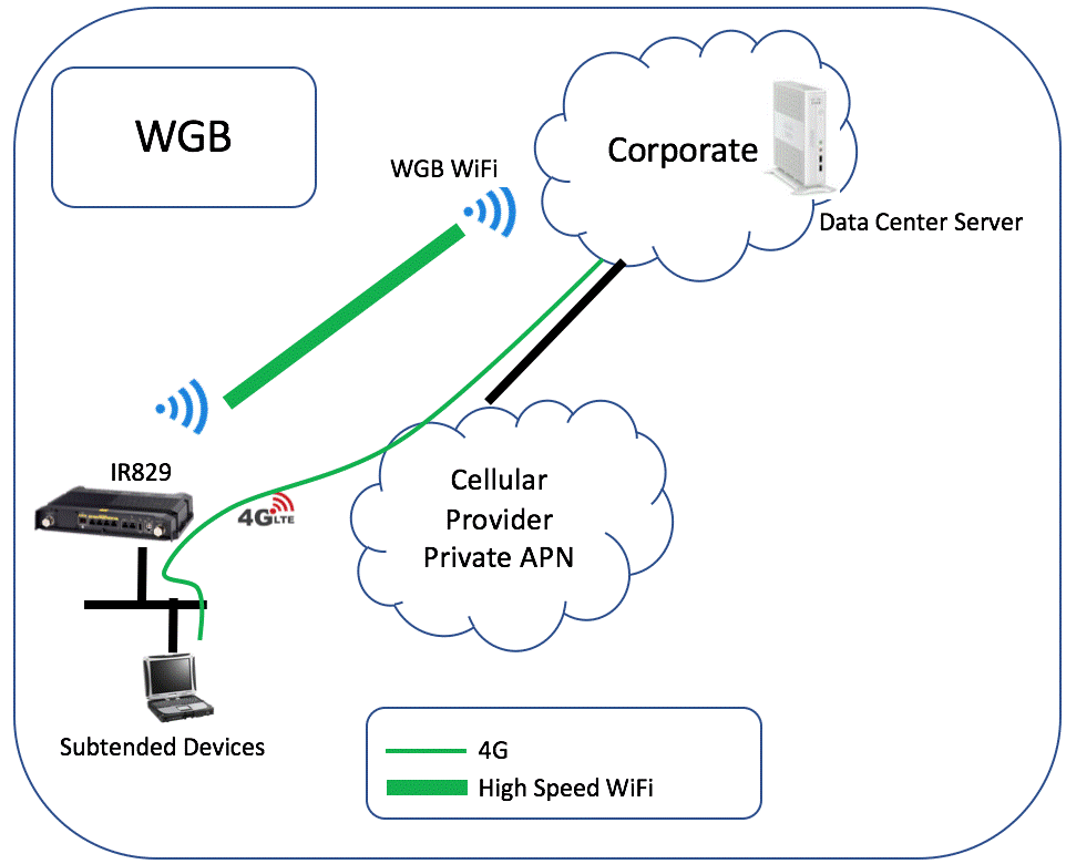
Use case
A vehicle has video data that needs to be uploaded. Once the vehicle pulls into the station or service center, the gateway connects to the enterprise WiFi network, which provides connectivity across the WiFi network for high speed data transfer. The GMM WGB feature only routes traffic destined to the “Restricted Subnet” network.
WiFi channel
The 5 GHz WiFi channel is used for the WGB. WiFi devices can still connect to the gateway's WiFi 2.4 GHz network.
| Setting | Description |
|---|---|
| Enabled | Allows the gateway to connect to an existing WiFi network. |
| SSID | The existing WiFi network used for Internet connectivity. |
| Pre-shared Key | The authentication key for the existing WiFi network (WGB SSID). |
| Restricted Subnet | (Optional) The destination network or host for data traffic. This destination will only be reachable through the WGB link. The traffic sent on this destination will be dropped when Work Group Bridge is down. |
See WGB troubleshooting for more information.
Dual LTE (IR829 gateways)
Dual LTE IR829 gateway models can use both SIM slots for cellular traffic.
Note: Changes to Dual LTE mode will interrupt network traffic.
| Setting | Description |
|---|---|
| Enable/Disable | When enabled, both SIMs in a Dual LTE gateway are used at the same time, according to the following settings. If Dual LTE is disabled, only one SIM is used at a time for cellular traffic (Active/Passive mode). |
| Check SIM 0/SIM 1 connectivity |
(Optional) Enter an IP address to verify SIM network connectivity. If blank, a default Cisco address is used. |
| Default Load Balancing | Cellular traffic is automatically balanced between the SIMs. For example, see CEF per destination load balancing. |
| Custom Load Balancing | Specify the subnet for traffic that will go out of SIM 1, as shown in the following illustration For example, if you have a video server you can send all video traffic out of SIM1. All other traffic will go out of SIM 0. |
Dual LTE Custom Load Balancing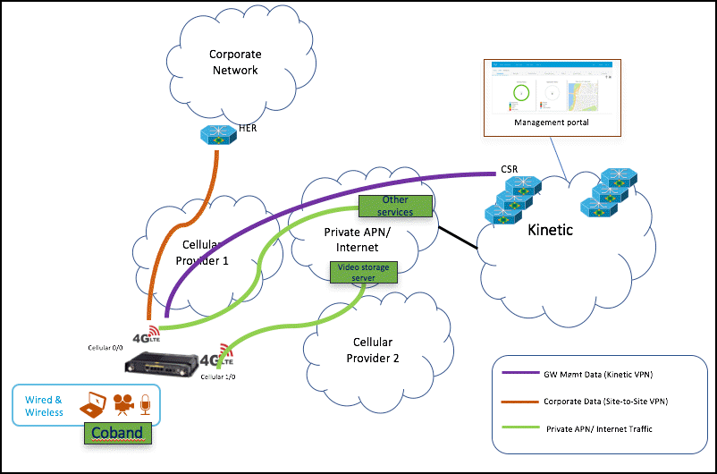
LAN ports
Allows devices to be connected to the gateway's Ethernet port. By default, LAN ports are enabled.
Disable the LAN ports to avoid unauthorized access if the subtended network on the gateway's Ethernet is not used.
IR829 gateway models
- The IR829 gateways support multiple LAN ports, which can be enabled or disabled individually.
- The LAN ports are different for the cellular and Ethernet gateways:
| Gateway | LAN ports |
|---|---|
| IR829 gateways | Gigabit Ethernet 1-4, if uplink is Cellular |
| IR829 gateways | Gigabit Ethernet 2-4, if uplink is Ethernet |
| IR809 gateways | GigabitEthernet 1 |
| IR807 gateways | FastEthernet 1 |
| IR1101 gateways | FastEthernet 1-4 |
GPS
Allows the gateway's GPS coordinates to be displayed on the dashboard map. The gateway must support GPS, have a GPS antenna installed, and receive a GPS signal from the GPS satellites (there should be direct line of sight from the antenna to the GPS satellite).
| Setting | Description |
|---|---|
| Enabled | The gateway's GPS coordinates are used to display the device location on the dashboard map. |
| Disabled | The address entered in gateway configuration is used to display the device location. |
Related topics:
Advanced Router Template
To learn more about Advanced Templates, see Advanced Templates
| Setting | Description |
|---|---|
| Fixed for all Gateways | Applies the template and variable definitions to the gateways when claimed. |
| Distinct per Gateway | Allows you to enter unique values for each gateway that uses the advanced template. After the gateway is claimed, go to Gateways, select a gateway and click the Networking Tab -> Advanced Configuration -> Advanced Templates. Then, enter values for the variables. |
| Select Template | Select a pre-defined template from the menu. |
| Variables | If the template includes variables, enter values for the variables, such as an IP address. |
Advanced AP Template
To learn more about Advanced Templates, see Advanced Templates
| Setting | Description |
|---|---|
| Fixed for all Gateways | Applies the template and variable definitions to the gateways when claimed. |
| Distinct per Gateway | Allows you to enter unique values for each gateway that uses the advanced template. After the gateway is claimed, go to Gateways, select a gateway and click the Networking Tab -> Advanced Configuration -> Advanced Templates. Then, enter values for the variables. |
| Select Template | Select a pre-defined template from the menu. |
| Variables | If the template includes variables, enter values for the variables, such as an IP address. |
Recovery Time
Select the amount of time that powered Gateways will wait after losing GMM connectivity before being automatically reset.
The gateway will erase the existing configuration, reload and attempt to reconfigure with the currently assigned GMM template config.