1. Documentation
  2. All
  3. Aironet Developer Platform
Aironet Developer Platform
  • Cisco Aironet Developer Platform Quick Start Guide
    • About Aironet Developer Platform
      • Development Process
      • About This Guide
    • Module Development Guidelines
      • Module Connectivity
      • Constraints
      • Design and Installation
    • HDK Block and Power Diagrams
      • Block Diagram
      • Power Diagram
    • HDK Elements
      • Specifications At-A-Glance
      • Ethernet
      • I2C/SMI Address Assignments
      • MAC Address Assignments
      • Serial IDPROM
      • Power and I/O Interfaces
        • Power and I/O Ports
        • Onboard Power Supplies
        • Power Input
        • Power Output
      • Signal Header and Control Pins
        • Ethernet Addresses and Signal Header Connections
        • Golden Finger Connector Pin Assignment
        • Headers and Control Pins
        • Power I/O Control
        • Sensor Control Pin
      • LED Indicators
    • HDK Mounting and Installation
      • Mounting and Installation
      • Mounting tray
      • Standoffs / Spacers
    • Single Board Computer Support
    • WLC Configuration
    • Additional Resources
      • IVT & Compliance
    • Community and Support
      • Developer Support
      • FAQs

Mounting and Installation

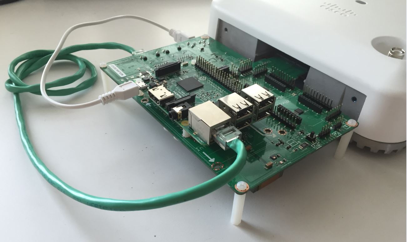
The HDK PCBA is primarily intended as an open-access prototyping board on a benchtop.

The HDK board must be mechanically supported when attached to the AP so a reliable host connection can be maintained.

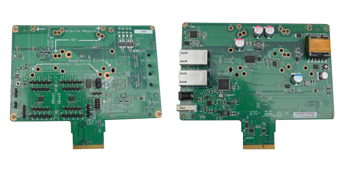
Figure 1: Cisco Aironet Developer Platform HDK (Rev2)

Mounting tray

A mounting tray is used to mount the HDK and attach to the AP as a single assembly. It is suitable for temporary attachment of the HDK to the AP when installed the ceiling or for more robust attactment to the AP for demonstation purposes.

Note The tray is not designed to support heavy modules from the ceiling such as an Intel NUC.

  • Four self-tapping screws secure the HDK PCB to the carrier.
  • Two 5/8" 8-32 screws attach the assembly to the AP.
Figure 3: HDK Mounting Tray

Note You may print your own HDK mounting tray by downloading the 3D sample mechanical files from the Additional Resources section.

Standoffs / Spacers

For development work on a desktop, use four 30mm M3 or 4-40 standoffs attached to the four corners of the HDK.

Note This solution is not intended for permanent installations.

Figure 4: Spacer
Next