1. Documentation
  2. All
  3. Aironet Developer Platform
Aironet Developer Platform
  • Cisco Aironet Developer Platform Quick Start Guide
    • About Aironet Developer Platform
      • Development Process
      • About This Guide
    • Module Development Guidelines
      • Module Connectivity
      • Constraints
      • Design and Installation
    • HDK Block and Power Diagrams
      • Block Diagram
      • Power Diagram
    • HDK Elements
      • Specifications At-A-Glance
      • Ethernet
      • I2C/SMI Address Assignments
      • MAC Address Assignments
      • Serial IDPROM
      • Power and I/O Interfaces
        • Power and I/O Ports
        • Onboard Power Supplies
        • Power Input
        • Power Output
      • Signal Header and Control Pins
        • Ethernet Addresses and Signal Header Connections
        • Golden Finger Connector Pin Assignment
        • Headers and Control Pins
        • Power I/O Control
        • Sensor Control Pin
      • LED Indicators
    • HDK Mounting and Installation
    • Single Board Computer Support
    • WLC Configuration
    • Additional Resources
      • IVT & Compliance
    • Community and Support
      • Developer Support
      • FAQs

HDK PCBA Power Diagram

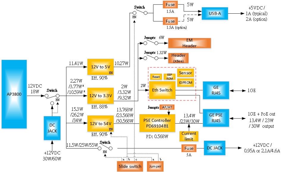
The following is a graphical representation of the electrical circuits, and the components and interconnections of the circuits, on the HDK. The presentation of the interconnections between circuit components in the schematic diagram does not necessarily correspond to the physical arrangements on the HDK.

Figure 7: HDK Power Diagram

Next