Add data destinations
Alert: Cisco has made the end-of-life (EOL) announcement for the Cisco Edge Intelligence.
Add data destinations to define where data policies send data, such as Azure IoT or MQTT. The data destination defines the connection details.
A destination must be set before designing and deploying data policies.
Existing data destinations can only be revised or deleted if they are not configured in any data policy.
Add a Microsoft Azure IoT Hub destination
To add a Microsoft Azure IoT destination, enter the parameters configured in the Azure IoT Hub Device Provisioning Service.
- From the left menu, click Data Destinations.
- In the right pane, click Add Data Destination and select Microsoft Azure IoT.
- Complete the following fields in the Add Data Destination – Azure IoT page and click Save.
| Field | Description |
|---|---|
| Data Destination Name | The name for the data destination. |
| Description | This is an optional field. |
| Azure IOT Connection Details | |
| ID Scope | The ID Scope that can be obtained from the Azure Device provisioning service Overview page. |
| CA Certificate | The intermediate CA Certificate file that you have configured in your Azure Device Provisioning Service as trustworthy. Note: The Status of this CA certificate inside Azure Provisioning Service must be Verified (marked as trusted) or device creation (and therefore metric sending) will not be allowed by Azure. |
| CA Certificate Key | The unencrypted private certificate key file that belongs to the intermediate CA specified under CA Certificate. The private-key must be in pkcs8 format. To convert an existing key, use the following command: openssl pkcs8 -topk8 -inform PEM -outform PEM -nocrypt -in azure-iot-test-only.intermediate.key.pem -out azure-iot-test-only.intermediate.pkcs8.pem Important: The key must not have a passphrase. |
| Advanced Settings | |
| Device Provisioning Endpoint | This is the same as your Global Device Endpoint from your Azure IOT Hub Device Provisioning Service. Note: In rare cases, you will need to change this field. |
| Enable MQTT over WebSockets | Check this to enable the browser to leverage all MQTT features. |
| Message Structure | Use this to customize the structure of the Device-to-Cloud message. Selecting and deselecting the Asset Attributes and Telemetry Data shows how the output data structure looks like in the Example section. The data can be sent in a flat structure or can be grouped with a key. Customization is not applicable if Data Policy is of type "Device Properties". |
Add an MQTT Server destination
EI has customized screens for specific MQTT based cloud destinations such as SAG Cumulocity IoT based on the MQTT parameters typically required for those implementations. A generic MQTT destination can be used for different configurations.
For example, a SAG Cumulocity destination that requires TLS and peer verification can be configured in EI. You can use a generic MQTT connection, however, to connect to a SAG Cumulocity IoT instance without TLS. For generic MQTT connections, make sure the configuration matches the destination instance requirements such as parameters, message format etc.
Usage notes:
- MQTT topic has a restricted number of characters that can be used in a topic name. For example, # or + cannot be part of a topic name. So, the contents of MQTT Topic field are URL-encoded so that the characters in the topic name do not violate the MQTT specification. URL-encoding was chosen as it is a widely used scheme and if required, the north-bound applications can decode it easily to get back the original contents.
- MQTT ClientID and X509 Client Cert CN do not have those limitations, so the contents of these fields are not URL-encoded.
To add an MQTT Server destination, complete the required fields.
- From the left menu, click Data Destinations.
- In the right pane, click Add Data Destination and select MQTT.
- Complete the following fields in the Add Data Destination – MQTT Broker page and click Save.
| Field | Description |
|---|---|
| Data Destination Name | The name for the data destination. |
| Description | This is an optional field. |
| Connection Details | |
| Broker | URL or IP address of your MQTT broker. |
| Port | The port number used by the broker. |
| Topic | The device states/data are published to this topic. For example, cisco/edge-intelligence/telemetry/%deviceSerialNumber%%deviceSerialNumber% will match the device/asset instance serial number configured previously in Assets tab. Refer to Add Asset Instances. The MQTT topic is configurable so you can include variables/placeholders that are dynamically replaced during the actual policy deployment: * ASSET_TYPE_LABEL—The label configured for the Asset Type. * POLICY_ID—An internally generated ID for the policy design. * POLICY_LABEL—The label configured for the policy. * AGENT_SERIAL—The agent's hardware serial number (also visible in the EI agent UI). * ASSET_SERIAL—The serial number entered in the asset config. * ASSET_NAME—The asset's name. * ATTRIBUTE_NAME—The custom attribute value with the asset name — ATTRIBUTE_NAME. Topic name is URL-encoded to ensure that it does not violate the MQTT specification. |
| Enable TLS | Select this checkbox to enable TLS. If you enable TLS, * Verify Peer Select this checkbox to allow peer verification. Then, in the Certificate field, choose a file or drag and drop to upload a CA Certificate. * Enable X.509 Select this checkbox to upload a CA certificate and private key for further verification. This allows you to turn on "Require Certificate" in MQTT Brokers (like Mosquitto). You can also use X509 client certs instead of username/password to ensure that only trusted assets are allowed to send data to a cloud MQTT broker. Notes: * The private key must be pkcs#8 compatible. * The generated certificate for each asset will contain the CN - Serial Number of the asset. * X.509 can be used in combination with Username/Password authentication or it can be used instead of it. |
| Username | The username to connect to the MQTT destination broker. |
| Password | The password to connect to the MQTT destination broker. |
| Advanced Settings | |
| QoS | Set the QoS policy to 0, 1 or 2 from the drop-down list. |
| Client ID | Enter the Client ID. For example, ${ASSET_SERIAL}_${POLICY_ID} The MQTT Client ID is configurable so you can include variables/placeholders that are dynamically replaced during the actual policy deployment: * ASSET_TYPE_LABEL—The label configured for the Asset Type. * POLICY_ID—An internally generated ID for the policy design. * POLICY_LABEL—The label configured for the policy. * AGENT_SERIAL—The agent's hardware serial number (also visible in the EI agent UI). * ASSET_SERIAL—The serial number entered in the asset config. * ASSET_NAME—The asset's name. * ATTRIBUTE_NAME—The custom attribute value with the asset name — ATTRIBUTE_NAME. The Client ID field is not URL-encoded since there are no restrictions in the MQTT specifications about the allowed characters. |
| Enable the following | Select Retain Messages. This option retains messages on the broker for new subscribers. |
| Message Structure | Use this to customize the structure of the Device-to-Cloud message. For example, you can: * Send custom attributes. * Use a custom attribute parent JSON container. * Timestamp telemetry events. * Use a telemetry data parent JSON container. Selecting and deselecting the Asset Attributes and Telemetry Data shows how the output data structure looks like in the Example section. The data can be sent in a flat structure or can be grouped with a key. Customization is not applicable if Data Policy is of type "Device Properties". |
| Cloud to Edge | |
| Enable cloud to data logic commands | Use the cloud to data logic commands to send a command (with payload) from a cloud app to the Data Logic on an Edge Device. The data logic script will parse the command. This feature provides bi-directional communication between the cloud and edge, allowing the app to send a command and receive a response. For example, a cold storage unit connected to an Edge device can send commands to: * set the temperature on the cold storage unit * initiate a de-frost action on the cold storage unit 1. Create an MQTT data destination. 2. Check the Enable cloud to data logic commands box. 3. Complete the following fields: * Command Topic: Enter the following syntax and variable in the format: cisco/edge-intelligence/commands/variable. Note: In the above format, commands and variables are optional. The supported variables are: * ${ASSET_TYPE_LABEL} = Label of the Asset Type * ${POLICY_ID} = ID of the Data Policy * ${POLICY_LABEL} = Label of the Data Policy * ${AGENT_SERIAL} = S/N of the EI Agent * ${ASSET_SERIAL} = S/N of the Asset * ${ASSET_NAME}—The asset's name. * ${ATTRIBUTE_NAME}—The custom attribute value with the asset name — ATTRIBUTE_NAME. For example: cisco/edge-intelligence/commands/${ASSET_SERIAL} * Response Topic: cisco/edge-intelligence/responses/variable The command response topic is editable. This is also optional (if the script doesn't send anything, nothing is published here). For example: thermo-fisher/Model-XYZ/commands/${ASSET_SERIAL} 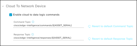 4. In Visual Studio IDE, select Runtime Options > Invoke on Cloud Command. 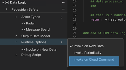 If we configure a pipeline with cloud commands, a new function needs to be defined in the script called on_cloud_command(). This function is called when we receive a command from the cloud. The command payload will be available to the user inside the on_cloud_command() function using the read-only output.command variable. See MQTT Cloud to Edge Messaging/Commands for more information. Example: function on_cloud_command() { if(output.command == "command_increment") { modbus.counter_1 = 1234 modbus.publish() // write to southbound } } |
Add a Software AG Cumulocity IoT destination
To add a Software AG Cumulocity IoT destination, complete the required fields.
- From the left menu, click Data Destinations.
- In the right pane, click Add Data Destination and then select Software AG Cumulocity IoT.
- Complete the following fields in the Add Data Destination – Cumulocity IoT page and click Save.
| Field | Description |
|---|---|
| Data Destination Name | The name for the data destination. |
| Description | This is an optional field. |
| Connection Details | |
| Broker | URL or IP address of your Software AG Cumulocity IoT MQTT broker. |
| Port | The port number used by the broker. |
| Topic | The device states/data are published to this topic. For example, cisco/edge-intelligence/telemetry/%deviceSerialNumber%%deviceSerialNumber% will match the device/asset instance serial number configured previously in Assets tab. Refer to Add Asset Instances. The Software AG Cumulocity IoT topic is configurable so you can include variables/placeholders that are dynamically replaced during the actual policy deployment: * ASSET_TYPE_LABEL—The label configured for the Asset Type. * POLICY_ID—An internal generated ID for the policy design. * POLICY_LABEL—The label configured for the policy. * AGENT_SERIAL—The agent's hardware serial number (also visible in the EI agent UI). * ASSET_SERIAL—The serial number entered in the asset config. . |
| Upload TLS Certificate | Choose a file or drag and drop to upload a CA Certificate. |
| Basic Aunthentication / Certificate Authentication | Select Basic Authentication and enter the username and password. |
| Advanced Settings | |
| QoS | Set the QoS policy to 0, 1 or 2 from the drop-down list. |
AWS Integration
This section describes how to set up AWS IoT Core as an EI destination.
Set up AWS
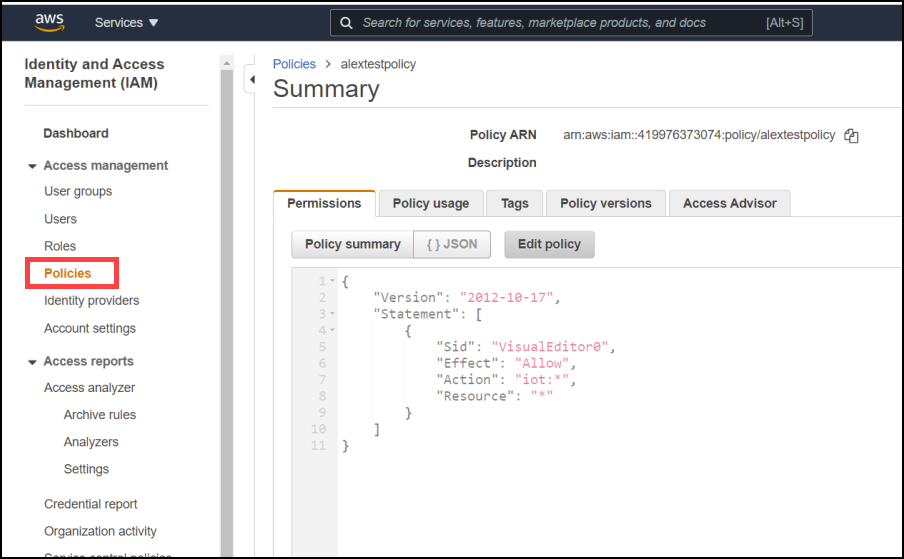
Set up the AWS IoT Core policy.

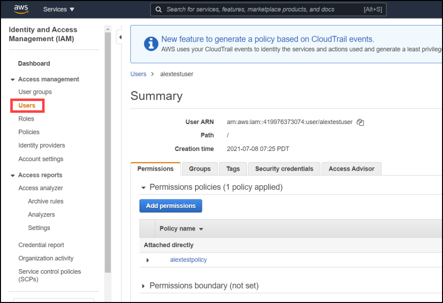
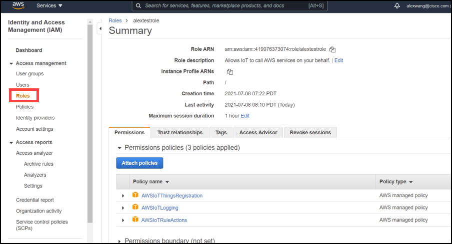
Enter the IAM role, policy, and user.
Generate certificates
- On a Windows PC, install git, and start git bash. Alternatively, install an openssl pre-built command.
- Generate a root certificate using the following commands.
openssl genrsa -out rootCA.key 4096

openssl pkcs8 -topk8 -inform PEM -outform PEM -nocrypt -in rootCA.key -out rootCA.pkcs8.pem
Note: The location of openssl.conf is per platform. For Windows, usually it is at “C:/program files/git/usr/openssl”.
openssl req -new -sha256 -key rootCA.key -nodes -out rootCA.csr -config openssl.conf

openssl x509 -req -sha256 -days 1024 -extfile openssl.cnf -extensions v3_ca -in rootCA.csr -signkey rootCA.key -out rootCA.pem
- Install the AWS Command Line, and then run this command:
Note: Before running the aws command, make sure the AWS region is the one you intend to use. For example, this command shows the current AWS region is us-east-1
$ aws configure get region

us-east-1

aws iot get-registration-code
You will get a response such as:
$ aws iot get-registration-code

{

    "registrationCode": "45ca145968423f1ce099b0019091a4f766f13823af4c72ffba2e9ced7130282d"

}
Save the generated registrationCode. It will be used later as the verification certificate CN.
- Within the git bash, execute the following commands:
openssl genrsa -out verificationCert.key 2048
When executing the command below to create a verification certificate, you will be asked to provide the CN. Copy the registrationCode previously generated by the "aws iot get-registration-code" and paste it as CN.
openssl req -new -key verificationCert.key -out verificationCert.csr

openssl x509 -req -in verificationCert.csr -CA rootCA.pem -CAkey rootCA.key -CAcreateserial -out verificationCert.pem -days 500 -sha256
The following command will use the provision_template.json. Update the example below and save it.
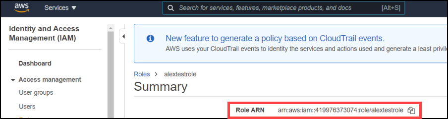
The policy name highlighted must match the IoT core policy you have just created. And the role is the IAM role just created (You will need the entire Role ARN).
{

  "templateBody": "{ \"Parameters\" : { \"AWS::IoT::Certificate::Id\" : { \"Type\" : \"String\" }, \"AWS::IoT::Certificate::CommonName\" : { \"Type\" : \"String\" } }, \"Resources\" : { \"thing\" : { \"Type\" : \"AWS::IoT::Thing\", \"Properties\" : { \"ThingName\" : {\"Ref\" : \"AWS::IoT::Certificate::CommonName\"}, \"AttributePayload\" : { \"version\" : \"v1\"} } }, \"certificate\" : { \"Type\" : \"AWS::IoT::Certificate\", \"Properties\" : { \"CertificateId\": {\"Ref\" : \"AWS::IoT::Certificate::Id\"}, \"Status\" : \"ACTIVE\" } }, \"policy\" : {\"Type\" : \"AWS::IoT::Policy\", \"Properties\" : { \"PolicyName\" : \"alexnewpolicy\" } } } }",

  "roleArn": "arn:aws:iam::419976373074:role/alextestrole"

}

aws iot register-ca-certificate --ca-certificate file://rootCA.pem --verification-cert file://verificationCert.pem --set-as-active --allow-auto-registration --registration-config file://provision_template.json
Create an AWS data destination in Cisco EI
- In the EI UI, from the left menu, click Data Destinations.
- In the right pane, click Add Data Destination and then select AWS IoT Core. You will be directed to the Add Data Destination – MQTT Broker page.
- Complete the fields in the Add Data Destination – MQTT page and click Save.
Under Connection Details:
broker: this info can be found from the AWS IoT Setting:
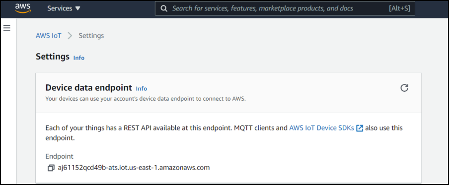
Port number should be 8883, QoS = 1, retain messages = de-selected.
Select enable TLS. Disable Verify Peer. Enable X.509. Upload the two files generated previously using openssl: rootCA.pem and rootCA.pkcs8.pem.
Leave the username and password blank.

Testing
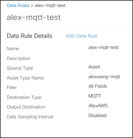
- From Cisco’s EI, create a new data rule policy. Refer to Create a Data Rule.
Note: Since the transport used by AWS is MQTT, select MQTT as destination type.
- Deploy this rule to an EI agent. Refer to Deploy Data Rules. If everything works well, you will get the policy status as All Running.

- On AWS, you can check the incoming data.

Manage data destinations
EI allows you to view, edit and delete a data destination.
View a data destination
- From the left pane, click Data Destinations.
- In the right pane, in the Data Destinations page, select a Data Destination to view its details.
Edit a data destination
Note: A data destination cannot be modified if it is used in an already deployed policy.
- From the left pane, click Data Destinations, then select a Data Destination to edit.
- In the Data Destination Details page, click Edit Data Destination to modify the required fields and click Save.
Delete a data destination
Note: A data destination cannot be deleted if it is used in an already deployed policy.
- From the left pane, click Data Destinations, then select a Data Destination to delete.
- Click Delete and then click Yes when prompted.