Up until this point, this user guide has described how to use NSO to configure devices. NSO can also manage the life-cycle for services like VPNs, BGP peers, ACLs. It is important to understand what is meant by service in this context.
-
NSO abstracts the device specific details. The user only needs to enter attributes relevant to the service.
-
The service instance has configuration data itself that can be represented and manipulated.
-
A service instance configuration change is applied to all affected devices.
These are the features NSO uses to support service configuration.
-
Service Modeling: network engineers can model the service attributes and the mapping to device configurations. For example, this means that a network engineer can specify at data-model for VPNs with router interfaces, VLAN id, VRF and route distinguisher.
-
Service life-cycle: while less sophisticated configuration management systems can only create an initial service instance in the network they do not support changing or deleting a service instance. With NSO you can at any point in time modify service elements like the VLAN id of a VPN and NSO can generate the corresponding changes to the network devices.
-
The NSO service instance has configuration data that can be represented and manipulated. The service model run-time updates all NSO northbound interfaces so a network engineer can view and manipulate the service instance over CLI, WebUI, REST etc.
-
NSO maintains references between service instances and device configuration. This means that a VPN instance knows exactly which device configurations it created/modified. Every configuration stored in the CDB is mapped to the service instance that created it.
An example is the best method to illustrate how services are created and used in NSO. As described in the sections about devices and NEDs it was said that NEDs come in packages. The same is true for services, either if you do design the services yourself or use ready-made service applications it ends up in a package that is loaded into NSO.
Tip
You can find a video presentation of this demo on YouTube.
The example
examples.ncs/service-provider/mpls-vpn will
be used to explain NSO Service Management features. This example
illustrates Layer3 VPNs in a service provider MPLS network.
The example network consists of Cisco ASR 9k and Juniper core
routers (P and PE) and Cisco IOS based CE routers.
The Layer3 VPN service configures the CE/PE routers for all
endpoints in the VPN with BGP as the CE/PE routing
protocol. Layer2 connectivity between CE and PE routers are
expected to be done through a Layer2 ethernet access network,
which is out of scope for this example.
The Layer3 VPN service includes VPN connectivity as well as
bandwidth and QOS parameters.
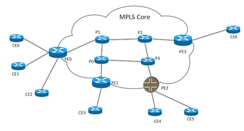
The service configuration only has references to CE devices for the end-points in the VPN. The service mapping logic reads from a simple topology model that is configuration data in NSO, outside the actual service model, and derives what other network devices to configure. The topology information has two parts. The first part lists connections in the network and is used by the service mapping logic to find out which PE router to configure for an endpoint. The snippets below show the configuration output in the Cisco style NSO CLI.
topology connection c0
 endpoint-1 device ce0 interface GigabitEthernet0/8 ip-address 192.168.1.1/30
 endpoint-2 device pe0 interface GigabitEthernet0/0/0/3 ip-address 192.168.1.2/30
 link-vlan 88
!
topology connection c1
 endpoint-1 device ce1 interface GigabitEthernet0/1 ip-address 192.168.1.5/30
 endpoint-2 device pe1 interface GigabitEthernet0/0/0/3 ip-address 192.168.1.6/30
 link-vlan 77
!
The second part lists devices for each role in the network and is in this example only used to dynamically render a network map in the Web UI.
topology role ce
 device [ ce0 ce1 ce2 ce3 ce4 ce5 ]
!
topology role pe
 device [ pe0 pe1 pe2 pe3 ]
!
QOS configuration in service provider networks is complex, and often require a lot of different variations. It is also often desirable to be able to deliver different levels of QOS. This example shows how a QOS policy configuration can be stored in NSO and be referenced from VPN service instances. Three different levels of QOS policies are defined; GOLD, SILVER and BRONZE with different queuing parameters.
 qos qos-policy GOLD
 class BUSINESS-CRITICAL
  bandwidth-percentage 20
 !
 class MISSION-CRITICAL
  bandwidth-percentage 20
 !
 class REALTIME
  bandwidth-percentage 20
  priority
 !
!
qos qos-policy SILVER
 class BUSINESS-CRITICAL
  bandwidth-percentage 25
 !
 class MISSION-CRITICAL
  bandwidth-percentage 25
 !
 class REALTIME
  bandwidth-percentage 10
 !
Three different traffic classes are also defined with a DSCP value that will be used inside the MPLS core network as well as default rules that will match traffic to a class.
qos qos-class BUSINESS-CRITICAL
 dscp-value af21
 match-traffic ssh
  source-ip      any
  destination-ip any
  port-start     22
  port-end       22
  protocol       tcp
 !
!
qos qos-class MISSION-CRITICAL
 dscp-value af31
 match-traffic call-signaling
  source-ip      any
  destination-ip any
  port-start     5060
  port-end       5061
  protocol       tcp
 !
!
Make sure you start clean, i.e. no old configuration data is present. If you have been running this or some other example before, make sure to stop any NSO or simulated network nodes (ncs-netsim) that you may have running. Output like 'connection refused (stop)' means no previous NSO was running and 'DEVICE ce0 connection refused (stop)...' no simulated network was running, which is good.
$make stop clean all start$ncs_cli -u admin -C
This will setup the environment and start the simulated network.
Before creating a new L3VPN service we must sync the configuration from all network devices and then enter config mode. (A hint for this complete section is to have the README file from the example and cut and paste the CLI commands).
ncs#devices sync-fromsync-result { device ce0 result true } ...ncs#configEntering configuration mode terminal ncs(config)# vpn l3vpn volvo ncs(config-l3vpn-volvo)#as-number 65101ncs(config-l3vpn-volvo)#endpoint main-officencs(config-endpoint-main-office)#ce-device ce0ncs(config-endpoint-main-office)#ce-interface GigabitEthernet0/11ncs(config-endpoint-main-office)#ip-network 10.10.1.0/24ncs(config-endpoint-main-office)#bandwidth 12000000ncs(config-endpoint-main-office)#!ncs(config-endpoint-main-office)#endpoint branch-office1ncs(config-endpoint-branch-office1)#ce-device ce1ncs(config-endpoint-branch-office1)#ce-interface GigabitEthernet0/11ncs(config-endpoint-branch-office1)#ip-network 10.7.7.0/24ncs(config-endpoint-branch-office1)#bandwidth 6000000ncs(config-endpoint-branch-office1)#!ncs(config-endpoint-branch-office1)#endpoint branch-office2ncs(config-endpoint-branch-office2)#ce-device ce4ncs(config-endpoint-branch-office2)#ce-interface GigabitEthernet0/18ncs(config-endpoint-branch-office2)#ip-network 10.8.8.0/24ncs(config-endpoint-branch-office2)#bandwidth 300000ncs(config-endpoint-branch-office2)#!ncs(config-endpoint-branch-office2)#topncs(config)#show configurationvpn l3vpn volvo as-number 65101 endpoint branch-office1 ce-device ce1 ce-interface GigabitEthernet0/11 ip-network 10.7.7.0/24 bandwidth 6000000 ! endpoint branch-office2 ce-device ce4 ce-interface GigabitEthernet0/18 ip-network 10.8.8.0/24 bandwidth 300000 ! endpoint main-office ce-device ce0 ce-interface GigabitEthernet0/11 ip-network 10.10.1.0/24 bandwidth 12000000 ! !ncs(config)#commit dry-run outformat nativenative { device { name ce0 data interface GigabitEthernet0/11 description volvo local network ip address 10.10.1.1 255.255.255.0 exit ... (config)#commit
Add another VPN (prompts ommitted):
top
!
vpn l3vpn ford
as-number 65200
endpoint main-office
ce-device    ce2
ce-interface GigabitEthernet0/5
ip-network   192.168.1.0/24
bandwidth    10000000
!
endpoint branch-office1
ce-device    ce3
ce-interface GigabitEthernet0/5
ip-network   192.168.2.0/24
bandwidth    5500000
!
endpoint branch-office2
ce-device    ce5
ce-interface GigabitEthernet0/5
ip-network   192.168.7.0/24
bandwidth    1500000
!
The above sequence showed how NSO can be used to manipulate service abstractions on top of devices. Services can be defined for various purpose such as VPNs, Access Control Lists, firewall rules etc. Support for services is added to NSO via a corresponding service package.
A service package in NSO comprises two parts:
-
Service model: the attributes of the service, input parameters given when creating the service. In this example name, as-number, and end-points.
-
Mapping: what is the corresponding configuration of the devices when the service is applied. The result of the mapping can be inspected by the commit dry-run outformat native command.
We later in this guide show how to define this, for now assume that the job is done.
When NSO applies services to the network, NSO stores the
service configuration along with resulting device
configuration changes. This is used as a base for the
FASTMAP algorithm which automatically can derive device
configuration changes from a service change. So going back
to the example L3 VPN above any part of volvo
VPN instance can be modified. A simple change like changing
the as-number on the service results in many
changes in the network. NSO does this automatically.
ncs(config)#vpn l3vpn volvo as-number 65102ncs(config-l3vpn-volvo)#commit dry-run outformat nativenative { device { name ce0 data no router bgp 65101 router bgp 65102 neighbor 192.168.1.2 remote-as 100 neighbor 192.168.1.2 activate network 10.10.1.0 ! ... ncs(config-l3vpn-volvo)#commit
Let us look at a more challenging modification. A common use-case is of course to add a new CE device and add that as an end-point to an existing VPN. Below follows the sequence to add two new CE devices and add them to the VPN's. (In the CLI snippets below we omit the prompt to enhance readability). First we add them to the topology.
top
!
topology connection c7
endpoint-1 device ce7 interface GigabitEthernet0/1 ip-address 192.168.1.25/30
endpoint-2 device pe3 interface GigabitEthernet0/0/0/2 ip-address 192.168.1.26/30
link-vlan 103
!
topology connection c8
endpoint-1 device ce8 interface GigabitEthernet0/1 ip-address 192.168.1.29/30
endpoint-2 device pe3 interface GigabitEthernet0/0/0/2 ip-address 192.168.1.30/30
link-vlan 104
!
ncs(config)#commit
Note well that the above just updates NSO local information on topological links. It has no effect on the network. The mapping for the L3 VPN services does a look-up in the topology connections to find the corresponding pe router.
Then we add them to the VPN's
top
!
vpn l3vpn ford
endpoint new-branch-office
ce-device    ce7
ce-interface GigabitEthernet0/5
ip-network   192.168.9.0/24
bandwidth    4500000
!
vpn l3vpn volvo
endpoint new-branch-office
ce-device    ce8
ce-interface GigabitEthernet0/5
ip-network   10.8.9.0/24
bandwidth    4500000
!
Before we send anything to the network, lets see look at the device configuration using dry-run. As you can see, both new CE devices are connected to the same PE router, but for different VPN customers.
ncs(config)#commit dry-run outformat nativeAnd commit the configuration to the network
(config)#commit
Next we will show how NSO can be used to check if the service configuration in the network is up to date. In a new terminal window we connect directly to the device ce0 that is a Cisco device emulated by the tool ncs-netsim.
$ ncs-netsim cli-c ce0We will now reconfigure an edge interface that we previously configured using NSO.
enable ce0#configureEnter configuration commands, one per line. End with CNTL/Z. ce0(config)#no policy-map volvoce0(config)#exitce0#exit
Going back to the terminal with NSO, check the status of the network configuration:
ncs#devices check-syncsync-result { device ce0 result out-of-sync info got: c5c75ee593246f41eaa9c496ce1051ea expected: c5288cc0b45662b4af88288d29be8667 ... ncs#vpn l3vpn * check-syncvpn l3vpn ford check-sync in-sync true vpn l3vpn volvo check-sync in-sync true ncs#vpn l3vpn * deep-check-syncvpn l3vpn ford deep-check-sync in-sync true vpn l3vpn volvo deep-check-sync in-sync false
The CLI sequence above performs 3 different comparisons:
-
Real device configuration versus device configuration copy in NSO CDB
-
Expected device configuration from service perspective and device configuration copy in CDB.
-
Expected device configuration from service perspective and real device configuration.
Notice that the service 'volvo' is out of sync from the service configuration. Use the check-sync outformat cli to see what the problem is:
ncs# vpn l3vpn volvo deep-check-sync outformat cli
cli  devices {
         devices {
             device ce0 {
                 config {
    +                ios:policy-map volvo {
    +                    class class-default {
    +                        shape {
    +                            average {
    +                                bit-rate 12000000;
    +                            }
    +                        }
    +                    }
    +                }
                 }
             }
         }
     }
Assume that a network engineer considers the real device configuration to be authoritative:
ncs# devices device ce0 sync-from
result true
And then restore the service:
ncs#vpn l3vpn volvo re-deploy dry-run { outformat native }native { device { name ce0 data policy-map volvo class class-default shape average 12000000 ! ! } } ncs#vpn l3vpn volvo re-deploy
In the same way as NSO can calculate any service configuration change it can also automatically delete the device configurations that resulted from creating services:
ncs(config)#no vpn l3vpn fordncs(config)#commit dry-runcli devices { device ce7 config { - ios:policy-map ford { - class class-default { - shape { - average { - bit-rate 4500000; - } - } - } - } ...
It is important to understand the two diffs shown above. The first diff as an
output to show configuration shows the diff at service level. The second diff shows
the output generated by NSO to clean up the device configurations.
Finally, we commit the changes to delete the service.
(config)# commit
Service instances live in the NSO data-store as well as a copy of the device configurations. NSO will maintain relationships between these two.
Show the configuration for a service
ncs(config)# show full-configuration vpn l3vpn
vpn l3vpn volvo
 as-number 65102
 endpoint branch-office1
  ce-device    ce1
  ce-interface GigabitEthernet0/11
  ip-network   10.7.7.0/24
  bandwidth    6000000
 !
...
You can ask NSO to list all devices that are touched by a service and vice versa:
ncs#show vpn l3vpn device-listNAME DEVICE LIST ---------------------------------------- volvo [ ce0 ce1 ce4 ce8 pe0 pe2 pe3 ] ncs#show devices device service-listNAME SERVICE LIST ------------------------------------- ce0 [ "/l3vpn:vpn/l3vpn{volvo}" ] ce1 [ "/l3vpn:vpn/l3vpn{volvo}" ] ce2 [ ] ce3 [ ] ce4 [ "/l3vpn:vpn/l3vpn{volvo}" ] ce5 [ ] ce6 [ ] ce7 [ ] ce8 [ "/l3vpn:vpn/l3vpn{volvo}" ] p0 [ ] p1 [ ] p2 [ ] p3 [ ] pe0 [ "/l3vpn:vpn/l3vpn{volvo}" ] pe1 [ ] pe2 [ "/l3vpn:vpn/l3vpn{volvo}" ] pe3 [ "/l3vpn:vpn/l3vpn{volvo}" ]
Note that operational mode in the CLI was used above. Every service instance has an operational attribute that is maintained by the transaction manager and shows which device configuration it created. Furthermore every device configuration has backwards pointers to the corresponding service instances:
ncs(config)#show full-configuration devices device ce3 \ config | display service-meta-datadevices device ce3 config ... /* Refcount: 1 */ /* Backpointer: [ /l3vpn:vpn/l3vpn:l3vpn[l3vpn:name='ford'] ] */ ios:interface GigabitEthernet0/2.100 /* Refcount: 1 */ description Link to PE / pe1 - GigabitEthernet0/0/0/5 /* Refcount: 1 */ encapsulation dot1Q 100 /* Refcount: 1 */ ip address 192.168.1.13 255.255.255.252 /* Refcount: 1 */ service-policy output ford exit ncs(config)#show full-configuration devices device ce3 config \ | display curly-braces | display service-meta-data... ios:interface { GigabitEthernet 0/1; GigabitEthernet 0/10; GigabitEthernet 0/11; GigabitEthernet 0/12; GigabitEthernet 0/13; GigabitEthernet 0/14; GigabitEthernet 0/15; GigabitEthernet 0/16; GigabitEthernet 0/17; GigabitEthernet 0/18; GigabitEthernet 0/19; GigabitEthernet 0/2; /* Refcount: 1 */ /* Backpointer: [ /l3vpn:vpn/l3vpn:l3vpn[l3vpn:name='ford'] ] */ GigabitEthernet 0/2.100 { /* Refcount: 1 */ description "Link to PE / pe1 - GigabitEthernet0/0/0/5"; encapsulation { dot1Q { /* Refcount: 1 */ vlan-id 100; } } ip { address { primary { /* Refcount: 1 */ address 192.168.1.13; /* Refcount: 1 */ mask 255.255.255.252; } } } service-policy { /* Refcount: 1 */ output ford; } } ncs(config)#show full-configuration devices device ce3 config \ | display service-meta-data | context-match Backpointerdevices device ce3 /* Refcount: 1 */ /* Backpointer: [ /l3vpn:vpn/l3vpn:l3vpn[l3vpn:name='ford'] ] */ ios:interface GigabitEthernet0/2.100 devices device ce3 /* Refcount: 2 */ /* Backpointer: [ /l3vpn:vpn/l3vpn:l3vpn[l3vpn:name='ford'] ] */ ios:interface GigabitEthernet0/5
The reference counter above makes sure that NSO will not delete shared resources until the last service instance is deleted. The context-match search is helpful, it displays the path to all matching configuration items.
As described in detail in the Device Manager the section called “Commit Queue” section the commit queue can be used to increase the transaction throughput. When the commit queue are for service activation the services will have states reflecting outstanding commit queue items.
Note
When committing a service using the commit queue in async mode the northbound system can not rely on the service being fully activated in the network when the activation requests returns.
We will now commit a vpn service using the commit queue and one device is down.
$ ncs-netsim stop ce0
DEVICE ce0 STOPPED
ncs(config)#show configurationvpn l3vpn volvo as-number 65101 endpoint branch-office1 ce-device ce1 ce-interface GigabitEthernet0/11 ip-network 10.7.7.0/24 bandwidth 6000000 ! endpoint main-office ce-device ce0 ce-interface GigabitEthernet0/11 ip-network 10.10.1.0/24 bandwidth 12000000 ! ! ncs#commit commit-queue asynccommit-queue-id 10777927137 Commit complete. ncs(config)# *** ALARM connection-failure: Failed to connect to device ce0: connection refused: Connection refused
This service is not provisioned fully in the network, since ce0 was down. It will stay in the queue either until the device starts responding or that an action is taken to remove the service or remove the item. The commit queue can be inspected. As shown below we see that we are waiting for ce0. Inspecting the queue item shows the outstanding configuration.
ncs#show devices commit-queue | notabdevices commit-queue queue-item 10777927137 age 1934 status executing kilo-bytes-size 2 devices [ ce0 ce1 pe0 ] transient-errors [ ce0 ] is-atomic true ncs#show vpn l3vpn volvo commit-queue | notabcommit-queue queue-item 1498812003922 status executing
The commit queue will constantly try to push the configuration towards the devices. The number of retry attempts and at what interval they occur can be configured.
ncs# show full-configuration devices global-settings commit-queue | details
devices global-settings commit-queue enabled-by-default false
devices global-settings commit-queue atomic true
devices global-settings commit-queue retry-timeout 30
devices global-settings commit-queue retry-attempts unlimited
If we start ce0 and inspect the queue we will see that the queue will finally be empty, and that the commit-queue status for the service is empty.
ncs#show devices commit-queue | notabdevices commit-queue queue-item 10777927137 age 3357 status executing kilo-bytes-size 2 devices [ ce0 ce1 pe0 ] transient-errors [ ce0 ] is-atomic true ncs#show devices commit-queue | notabdevices commit-queue queue-item 10777927137 age 3359 status executing kilo-bytes-size 2 devices [ ce0 ce1 pe0 ] is-atomic true ncs#show devices commit-queue% No entries found. ncs#show vpn l3vpn volvo commit-queue% No entries found. ncs#show devices commit-queue completed | notabdevices commit-queue completed queue-item 10777927137 when 2015-02-09T16:48:17.915+00:00 succeeded true devices [ ce0 ce1 pe0 ] completed [ ce0 ce1 pe0 ] completed-services [ /l3vpn:vpn/l3vpn:l3vpn[l3vpn:name='volvo'] ]
In some scenarios it makes sense to remove the service configuration from the network but keep the representation of the service in NSO. This is called to un-deploy a service.
ncs#vpn l3vpn volvo check-syncin-sync false ncs#vpn l3vpn volvo re-deployncs#vpn l3vpn volvo check-syncin-sync true
Some services need to be set up in stages where each stage can consist of setting up some device configuration and then wait for this configuration to take effect before performing next stage. In this scenario each stage must be performed in a separate transaction which is committed separately. Most often an external notification or other event must be detected and trigger the next stage in the service activation.
NSO supports the implementation of such staged services with the use of a Reactive FASTMAP pattern, and the services are often referred to as RFM services.
From the user perspective it is not important how a certain service is implemented. And the implementation should not have an impact on how the user creates or modifies a service. However the knowledge about this can be necessary to explain the behavior of a certain service.
In short the life-cycle of a RFM service in not only controlled by
the direct create/set/delete operations. Instead there are one or
many implicit reactive-re-deploy requests on the
service that are triggered from external event detection.
If the user examines a RFM service, e.g. using
get-modification, the device impact will grow over
time after the initial create.
Reactive Fastmap (RFM) services autonomously will do
reactive-re-deploy until all "stages" of the service
are completed. This implies that an RFM service normally is not
completed when the initial create is committed.
For the operator to understand that a RFM service has run to
completion there must typically be some service specific
operational data that can indicate this.
Plans are introduced to standardize the operational data that can show the progress of RFM service. This gives the user a standardized view of all RFM services and can directly answer the question weather a service instance has run to completion or not.
A plan consists of one or many component entries. Each component consists of two or many state entries where the state can be in status not-reached, reached or failed. A plan must have a component named "self" and can have other components with arbitrary names that have meaning for the implementing RFM service. A plan component must have a first state named "init" and a last state named "ready". In between "init" and "ready" a plan component can have additional state entries with arbitrary naming.
The purpose of the "self" component is to describe the main progress of the RFM service as a whole. Most importantly the "self" component last state named "ready" must have status "reached" if and only if the RFM service as a whole has completed. Other arbitrary components as well as states are added to the plan if they have meaning for the specific RFM service i.e more specific progress reporting.
A plan also defines an empty leaf failed which is set if and only if any state in any component has a status set to "failed". As such this is an aggregation to make it easy to verify if a RFM service is progressing without problems or not.
The following is an illustration of using the plan to report progress of an RFM service:
ncs# show vpn l3vpn volvo plan
NAME                    TYPE   STATE              STATUS       WHEN
------------------------------------------------------------------------------------
self                    self   init               reached      2016-04-08T09:22:40
                               ready              not-reached  -
endpoint-branch-office  l3vpn  init               reached      2016-04-08T09:22:40
                               qos-configured     reached      2016-04-08T09:22:40
                               ready              reached      2016-04-08T09:22:40
endpoint-head-office    l3vpn  init               reached      2016-04-08T09:22:40
                               pe-created         not-reached  -
                               ce-vpe-topo-added  not-reached  -
                               vpe-p0-topo-added  not-reached  -
                               qos-configured     not-reached  -
                               ready              not-reached  -
Plans were introduced to standardize the operational data that show progress of reactive fastmap (RFM) services. This gives the user a standardized view of all RFM services and can answer the question weather a service instance has run to completion or not. To keep track of the progress of plans service progress monitoring (SPM) is introduced. The idea with SPM is that time limits are put on the progress of plan states. To do so, a policy and a trigger is needed.
A policy defines what plan components and states needs to be in what status for the policy to be true. A policy also defines how long time it can be false without considered jeopardized and how long time it can be false without considered violated. Further it may define an action, that is called in case of a policy being jeopardized, violated or successful.
A trigger is used to associate a policy with a service and a component.
The following is an illustration of using a SPM to track progress of an RFM service, in this case the policy specifies that the self components ready state must be reached for the policy to be true:
ncs# show vpn l3vpn volvo service-progress-monitoring
                                                               JEOPARDY                       VIOLATION           SUCCESS
NAME  POLICY         START TIME           JEOPARDY TIME        RESULT    VIOLATION TIME       RESULT     STATUS   TIME
---------------------------------------------------------------------------------------------------------------------------
self  service-ready  2016-04-08T09:22:40  2016-04-08T09:22:40  -         2016-04-08T09:22:40  -          running  -