This documentation corresponds to an older version of the product, is no longer updated, and may contain outdated information.
Please access the latest versions from https://cisco-tailf.gitbook.io/nso-docs and update your bookmarks. OK
As using Java for service development may be somewhat more involved than Python, this chapter provides further examples and additional tips for setting up development environment for Java.
The two examples, a simple VLAN service and a Layer 3 MPLS VPN service, are more elaborate but show the same techniques as Implementing Services. If you or your team primarily focuses on services implemented in Python, feel free to skip or only skim through this chapter.
In this example, you will create a simple VLAN service in Java. In order to illustrate the concepts, the device configuration is simplified from a networking perspective and only uses one single device type (Cisco IOS).
We will first look at the following preparatory steps:
-
Prepare a simulated environment of Cisco IOS devices: in this example we start from scratch in order to illustrate the complete development process. We will not reuse any existing NSO examples.
-
Generate a template service skeleton package: use NSO tools to generate a Java based service skeleton package.
-
Write and test the VLAN Service Model.
-
Analyze the VLAN service mapping to IOS configuration.
These steps are no different from defining services using templates. Next is to start playing with the Java Environment:
-
Configuring start and stop of the Java VM.
-
First look at the Service Java Code: introduction to service mapping in Java.
-
Developing by tailing log files.
-
Developing using Eclipse.
We will start by setting up a run-time environment that includes
simulated Cisco IOS devices and configuration data for NSO. Make
sure you have sourced the ncsrc file. Create
a new directory that will contain the files for this example, such as:
$mkdir ~/vlan-service$cd ~/vlan-service
Now lets create a simulated environment with 3 IOS devices and a NSO that is ready to run with this simulated network:
$ncs-netsim create-network $NCS_DIR/packages/neds/cisco-ios 3 c$ncs-setup --netsim-dir ./netsim/ --dest ./
Start the simulator and NSO:
$ncs-netsim startDEVICE c0 OK STARTED DEVICE c1 OK STARTED DEVICE c2 OK STARTED $ncs
Use the Cisco CLI towards one of the devices:
$ncs-netsim cli-i c0admin connected from 127.0.0.1 using console on ncs c0>enablec0#configureEnter configuration commands, one per line. End with CNTL/Z. c0(config)#show full-configurationno service pad no ip domain-lookup no ip http server no ip http secure-server ip routing ip source-route ip vrf my-forward bgp next-hop Loopback 1 ! ...
Use the NSO CLI to get the configuration:
$ncs_cli -C -u adminadmin connected from 127.0.0.1 using console on ncs admin@ncs#devices sync-fromsync-result { device c0 result true } sync-result { device c1 result true } sync-result { device c2 result true } admin@ncs#configEntering configuration mode terminal admin@ncs(config)#show full-configuration devices device c0 configdevices device c0 config no ios:service pad ios:ip vrf my-forward bgp next-hop Loopback 1 ! ios:ip community-list 1 permit ios:ip community-list 2 deny ios:ip community-list standard s permit no ios:ip domain-lookup no ios:ip http server no ios:ip http secure-server ios:ip routing ...
Finally, set VLAN information manually on a device to prepare for the mapping later.
admin@ncs(config)#devices device c0 config ios:vlan 1234admin@ncs(config)#devices device c0 config ios:interface FastEthernet 1/0 switchport mode trunkadmin@ncs(config-if)#switchport trunk allowed vlan 1234admin@ncs(config-if)#topadmin@ncs(config)#show configurationdevices device c0 config ios:vlan 1234 ! ios:interface FastEthernet1/0 switchport mode trunk switchport trunk allowed vlan 1234 exit ! ! admin@ncs(config)#commit
In the run-time directory you created:
$ ls -F1
README.ncs
README.netsim
logs/
ncs-cdb/
ncs.conf
netsim/
packages/
scripts/
state/
Note the packages directory,
cd to it:
$cd packages$ls -ltotal 8 cisco-ios -> .../packages/neds/cisco-ios
Currently there is only one package, the Cisco IOS NED. We will now create a new package that will contain the VLAN service.
$ncs-make-package --service-skeleton java vlan$lscisco-ios vlan
This creates a package with the following structure:
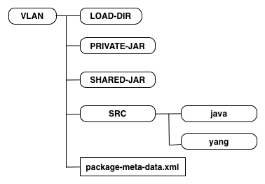
During the rest of this section we will work with the
vlan/src/yang/vlan.yang and
vlan/src/java/src/com/example/vlan/vlanRFS.java files.
So, if a user wants to create a new VLAN in the network what
should the parameters be?
Edit the vlan/src/yang/vlan.yang according to below:
  augment /ncs:services {
    list vlan {
      key name;

      uses ncs:service-data;
      ncs:servicepoint "vlan-servicepoint";
      leaf name {
        type string;
      }

      leaf vlan-id {
        type uint32 {
          range "1..4096";
        }
      }

      list device-if {
        key "device-name";
          leaf device-name {
            type leafref {
              path "/ncs:devices/ncs:device/ncs:name";
            }
          }
          leaf interface {
            type string;
          }
      }
    }
  }
This simple VLAN service model says:
-
We give a VLAN a name, for example
net-1 -
The VLAN has an id from 1 to 4096
-
The VLAN is attached to a list of devices and interfaces. In order to make this example as simple as possible the interface name is just a string. A more correct and useful example would specify this is a reference to an interface to the device, but for now it is better to keep the example simple.
The vlan service list is augmented into the services tree in NSO. This specifies the path to reach vlans in the CLI, REST etc. There is no requirements on where the service shall be added into ncs, if you want vlans to be at the top-level, just remove the augments statement.
Make sure you keep the lines generated by the ncs-make-package:
uses ncs:service-data;
ncs:servicepoint "vlan-servicepoint";
The two lines tell NSO that this is a service. The first line expands to a YANG structure that is shared amongst all services. The second line connects the service to the Java callback.
To build this service model cd to
packages/vlan/src and type make
(assumes you have the prerequisite make build system installed).
$cd packages/vlan/src/$make
We can now test the service model by requesting NSO to reload all packages:
$ncs_cli -C -U adminadmin@ncs#packages reload>>> System upgrade is starting. >>> Sessions in configure mode must exit to operational mode. >>> No configuration changes can be performed until upgrade has completed. >>> System upgrade has completed successfully. result Done
You can also stop and start NSO, but then you have to pass the
option --with-package-reload when starting
NSO. This is important, NSO does not by default take any changes in
packages into account when restarting. When packages are reloaded
the state/packages-in-use is updated.
Now, create a VLAN service, (nothing will happen since we have not defined any mapping).
admin@ncs(config)#services vlan net-0 vlan-id 1234 device-if c0 interface 1/0admin@ncs(config-device-if-c0)#topadmin@ncs(config)#commit
Now let us move on and connect that to some device configuration using Java mapping. Note well that Java mapping is not needed, templates are more straight-forward and recommended but we use this as a "Hello World" introduction to Java service programming in NSO. Also at the end we will show how to combine Java and templates. Templates are used to define a vendor independent way of mapping service attributes to device configuration and Java is used as a thin layer before the templates to do logic, call-outs to external systems etc.
The default configuration of the Java VM is:
admin@ncs(config)# show full-configuration java-vm | details
java-vm stdout-capture enabled
java-vm stdout-capture file ./logs/ncs-java-vm.log
java-vm connect-time           60
java-vm initialization-time    60
java-vm synchronization-timeout-action log-stop
java-vm jmx jndi-address 127.0.0.1
java-vm jmx jndi-port 9902
java-vm jmx jmx-address 127.0.0.1
java-vm jmx jmx-port 9901
By default, ncs will start the Java VM invoking the command $NCS_DIR/bin/ncs-start-java-vm That script will invoke
$ java com.tailf.ncs.NcsJVMLauncher
The class NcsJVMLauncher contains the
main() method. The started Java VM will automatically
retrieve and deploy all Java code for the packages defined in the
load-path of the ncs.conf file. No other
specification than the package-meta-data.xml
for each package is needed.
The verbosity of Java error messages can be controlled by:
admin@ncs(config)# java-vm exception-error-message verbosity
Possible completions:
  standard  trace  verbose
For more detail on the Java VM settings see The NSO Java VM.
The service model and the corresponding Java callback is bound by
the service point name. Look at the service model in
packages/vlan/src/yang:
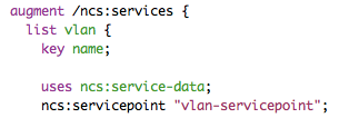
The corresponding generated Java skeleton, (one print hello world
statement added):
Modify the generated code to include the print "Hello World!" statement in the same way. Re-build the package:
$cd packages/vlan/src/$make
Whenever a package has changed we need to tell NSO to reload the package. There are three ways:
-
Just reload the implementation of a specific package, will not load any model changes: admin@ncs# packages package vlan redeploy
-
Reload all packages including any model changes: admin@ncs# packages reload
-
Restart NSO with reload option: $ncs --with-package-reload
When that is done we can create a service (or modify an existing) and the callback will be triggered:
admin@ncs(config)#vlan net-0 vlan-id 888admin@ncs(config-vlan-net-0)#commit
Now, have a look in the logs/ncs-java-vm.log:
$ tail ncs-java-vm.log
...
<INFO> 03-Mar-2014::16:55:23.705 NcsMain JVM-Launcher: \
       - REDEPLOY PACKAGE COLLECTION  --> OK
<INFO> 03-Mar-2014::16:55:23.705 NcsMain JVM-Launcher: \
       - REDEPLOY ["vlan"] --> DONE
<INFO> 03-Mar-2014::16:55:23.706 NcsMain JVM-Launcher: \
       - DONE COMMAND --> REDEPLOY_PACKAGE
<INFO> 03-Mar-2014::16:55:23.706 NcsMain JVM-Launcher: \
       - READ SOCKET =>
Hello World!
Tailing the ncs-java-vm.log is one way of
developing. You can also start and stop the Java VM explicitly and
see the trace in the shell. To do this, tell NSO not to start the
VM by adding the following snippet to ncs.conf:
<java-vm>
    <auto-start>false</auto-start>
</java-vm>
Then, after restarting NSO or reloading the configuration, from the shell prompt:
$ ncs-start-java-vm
.....
.. all stdout from JVM
So modifying or creating a VLAN service will now have the "Hello World!" string show up in the shell. You can modify the package and reload/redeploy and see the output.
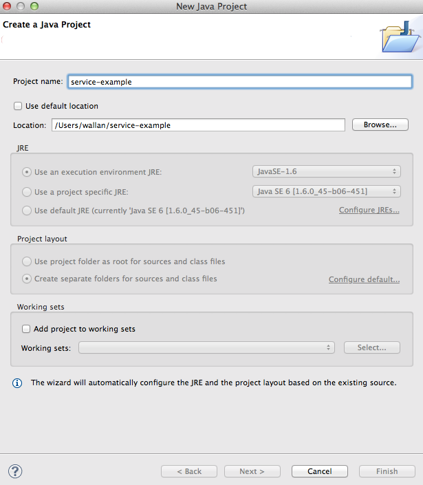
To use a GUI-based IDE Eclipse, first generate environment for Eclipse:
$ ncs-setup --eclipse-setup
This will generate two files, .classpath and
.project. If we add this directory to eclipse
as a "File->New->Java Project", uncheck the "Use the default
location" and enter the directory where the .classpath and
.project have been generated. We are immediately ready to run this
code in eclipse.
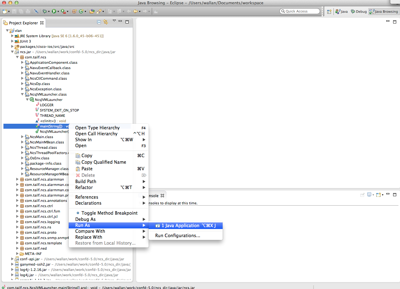
All we need to do is to choose the main() routine in
the NcsJVMLauncher class.
The eclipse debugger works now as usual, and we can at will start
and stop the Java code.
One caveat here which is worth mentioning is that there are a few timeouts between NSO and the Java code that will trigger when we sit in the debugger. While developing with the Eclipse debugger and breakpoints we typically want to disable all these timeouts. First we have 3 timeouts in ncs.conf that matter. Set the three values of /ncs-config/japi/new-session-timeout /ncs-config/japi/query-timeout /ncs-config/japi/connect-timeout to a large value. See man page ncs.conf(5) for a detailed description on what those values are. If these timeouts are triggered, NSO will close all sockets to the Java VM and all bets are off.
$ cp $NCS_DIR/etc/ncs/ncs.conf .Edit the file and enter the following XML entry just after the Webui entry.
<japi>
    <new-session-timeout>PT1000S</new-session-timeout>
    <query-timeout>PT1000S</query-timeout>
    <connect-timeout>PT1000S</connect-timeout>
</japi>
Now restart ncs, and from now on start it as
$ ncs -c ./ncs.confYou can verify that the Java VM is not running by checking the package status:
admin@ncs# show packages package vlan
packages package vlan
 package-version 1.0
 description     "Skeleton for a resource facing service - RFS"
 ncs-min-version 3.0
 directory       ./state/packages-in-use/1/vlan
 component RFSSkeleton
  callback java-class-name [ com.example.vlan.vlanRFS ]
 oper-status java-uninitialized
Create a new project and start the launcher main in Eclipse:
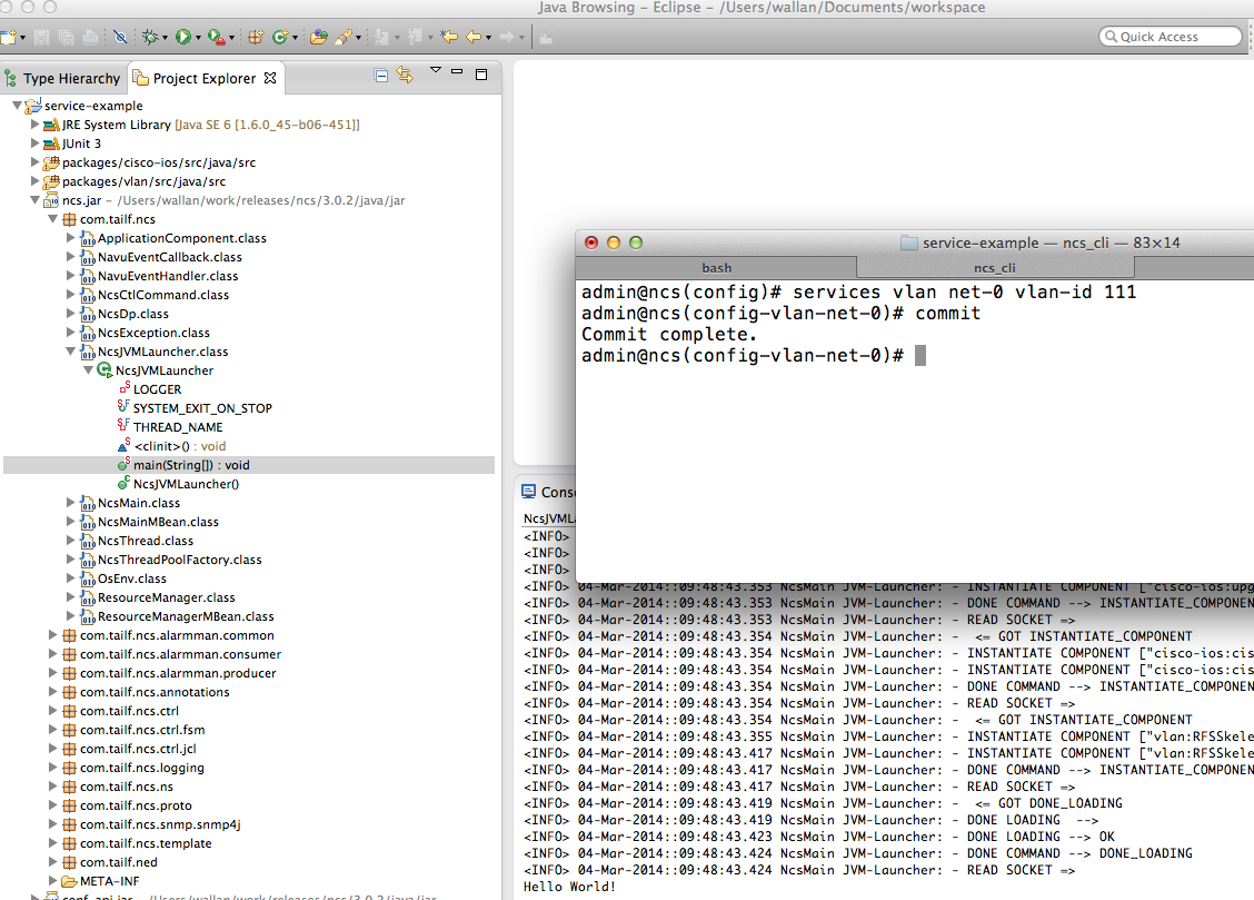
You can start and stop the Java VM from Eclipse. Note well that
this is not needed since the change cycle is: modify the Java
code, make in the src directory and then reload the package. All
while NSO and the JVM is running.
Change the VLAN service and see the console output in Eclipse:
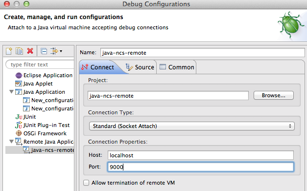
Another option is to have Eclipse connect to the running VM. Start the VM manually with the -d option.
$ ncs-start-java-vm -d
Listening for transport dt_socket at address: 9000
NCS JVM STARTING
...
Then you can setup Eclipse to connect to the NSO Java VM:
In order for Eclipse to show the NSO code when debugging add the
NSO Source Jars, (add external Jar in Eclipse):
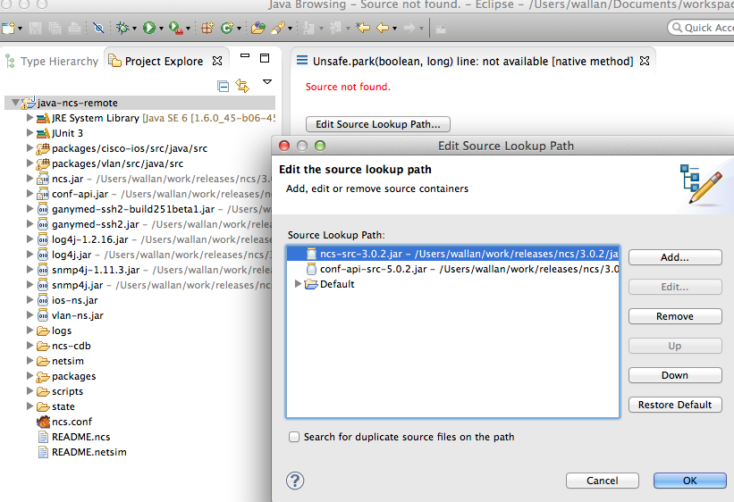
Navigate to the service create for the VLAN service and add a breakpoint:
Commit a change of a VLAN service instance and Eclipse will stop
at the breakpoint:

So the problem at hand is that we have service parameters and a resulting device configuration. Previously we showed how to do that with templates. The same principles apply in Java. The service model and the device models are YANG models in NSO irrespective of the underlying protocol. The Java mapping code transforms the service attributes to the corresponding configuration leafs in the device model.
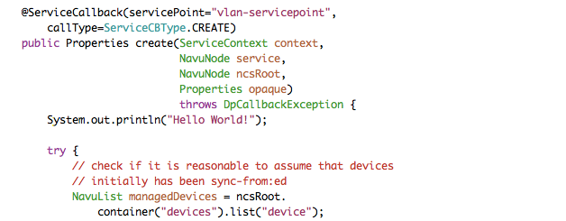
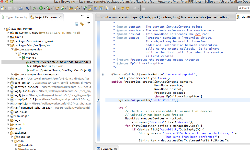
The NAVU API lets the Java programmer navigate the service model and the device models as a DOM tree. Have a look at the create signature:
 @ServiceCallback(servicePoint="vlan-servicepoint",
        callType=ServiceCBType.CREATE)
    public Properties create(ServiceContext context,
                             NavuNode service,
                             NavuNode ncsRoot,
                             Properties opaque)
                             throws DpCallbackException {
Two NAVU nodes are passed: the actual service
serviceinstance and the NSO root
ncsRoot.
We can have a first look at NAVU be analyzing the first try statement:
try {
            // check if it is reasonable to assume that devices
            // initially has been sync-from:ed
            NavuList managedDevices =
            ncsRoot.container("devices").list("device");
            for (NavuContainer device : managedDevices) {
                if (device.list("capability").isEmpty()) {
                    String mess = "Device %1$s has no known capabilities, " +
                                   "has sync-from been performed?";
                    String key = device.getKey().elementAt(0).toString();
                    throw new DpCallbackException(String.format(mess, key));
                }
            }
NAVU is a lazy evaluated DOM tree that represents the
instantiated YANG model. So knowing the NSO model:
devices/device, (container/list)
corresponds to the list of capabilities for a device, this can be
retrieved by
ncsRoot.container("devices").list("device").
The service node can be used to fetch the values of
the VLAN service instance:
-
vlan/name
-
vlan/vlan-id
-
vlan/device-if/device and vlan/device-if/interface
A first snippet that iterates the service model and prints to the console looks like below:
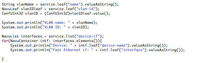
The com.tailf.conf package contains Java Classes
representing the YANG types like ConfUInt32.
Try it out by the following sequence:
-
Rebuild the Java Code : in
packages/vlan/srctype make. -
Reload the package : in the NSO Cisco CLI do admin@ncs# packages package vlan redeploy.
-
Create or modify a vlan service: in NSO CLI admin@ncs(config)# services vlan net-0 vlan-id 844 device-if c0 interface 1/0, and commit.
Remember the service attribute is passed as a
parameter to the create method. As a starting point, look at the
first three lines:
-
To reach a specific leaf in the model use the NAVU leaf method with the name of the leaf as parameter. This leaf then has various methods like getting the value as a string.
-
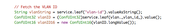
service.leaf("vlan-id")andservice.leaf(vlan._vlan_id_)are two ways of referring to the vlan-id leaf of the service. The latter alternative uses symbols generated by the compilation steps. If this alternative is used, you get the benefit of compilation time checking. From this leaf you can get the value according to the type in the YANG modelConfUInt32in this case. -
Line 3 shows an example of casting between types. In this case we prepare the VLAN ID as a 16 unsigned int for later use.
Next step is to iterate over the devices and interfaces. The NAVU
elements() returns the elements of a NAVU list.
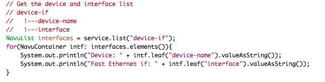
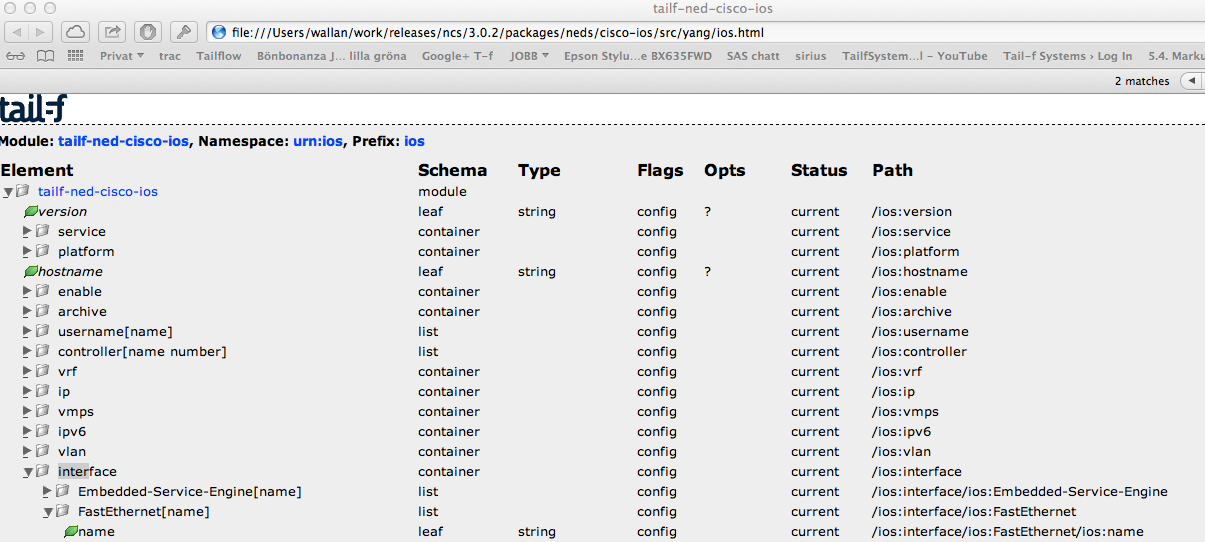
In order to write the mapping code, make sure you have an understanding of the device model. One good way of doing that is to create a corresponding configuration on one device and then display that with pipe target "display xpath". Below is a CLI output that shows the model paths for "FastEthernet 1/0":
admin@ncs% show devices device c0 config ios:interface
           FastEthernet 1/0 | display xpath

/devices/device[name='c0']/config/ios:interface/
         FastEthernet[name='1/0']/switchport/mode/trunk

/devices/device[name='c0']/config/ios:interface/
         FastEthernet[name='1/0']/switchport/trunk/allowed/vlan/vlans [ 111 ]
Another useful tool is to render a tree view of the model:
$ pyang -f jstree tailf-ned-cisco-ios.yang -o ios.htmlThis can then be opened in a Web browser and model paths are shown to the right:
Now, we replace the print statements with setting real configuration on the devices.
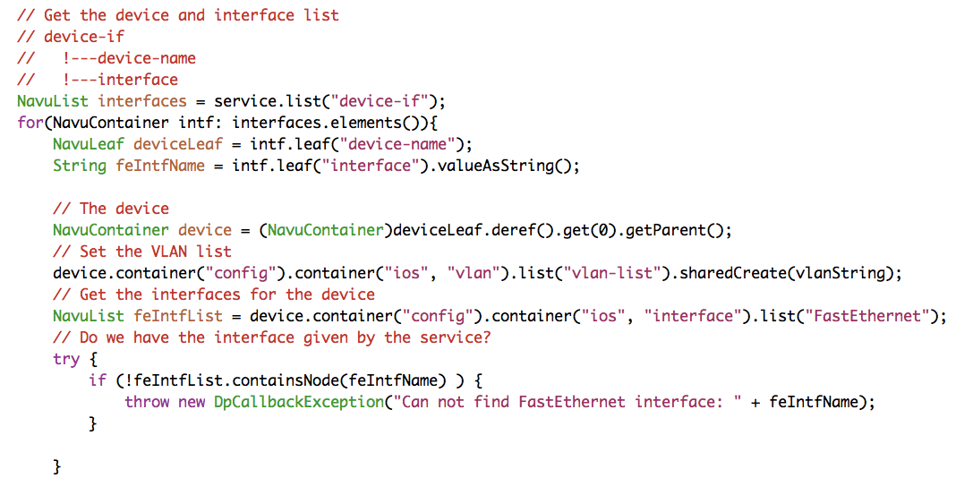
Let us walk through the above code line by line. The
device-name is a leafref. The
deref method returns the object that the
leafref refers to. The getParent() might
surprise the reader. Look at the path for a leafref:
/device/name/config/ios:interface/name. The
name leafref is the key that identifies a specific
interface. The deref returns that key, while we want to
have a reference to the interface,
(/device/name/config/ios:interface), that is the reason
for the getParent().
The next line sets the vlan-list on the device. Note well that this
follows the paths displayed earlier using the NSO CLI. The
sharedCreate() is important, it creates device
configuration based on this service, and it says that other services
might also create the same value, "shared". Shared create maintains
reference counters for the created configuration in order for the
service deletion to delete the configuration only when the last
service is deleted. Finally the interface name is used as a key to
see if the interface exists, "containsNode()".
The last step is to update the VLAN list for each interface. The
code below adds an element to the VLAN leaf-list.
// The interface
NavuNode theIf = feIntfList.elem(feIntfName);
theIf.container("switchport").
      sharedCreate().
      container("mode").
      container("trunk").
      sharedCreate();
// Create the VLAN leaf-list element
theIf.container("switchport").
      container("trunk").
      container("allowed").
      container("vlan").
      leafList("vlans").
      sharedCreate(vlanID16);
Note that the code uses the sharedCreate() functions
instead of create(), as the shared variants are
preferred and a best practice.
The above create method is all that is needed for create, read, update and delete. NSO will automatically handle any changes, like changing the VLAN ID, adding an interface to the VLAN service and deleting the service. This is handled by the FASTMAP engine, it renders any change based on the single definition of the create method.
The mapping strategy using only Java is illustrated in the following figure.
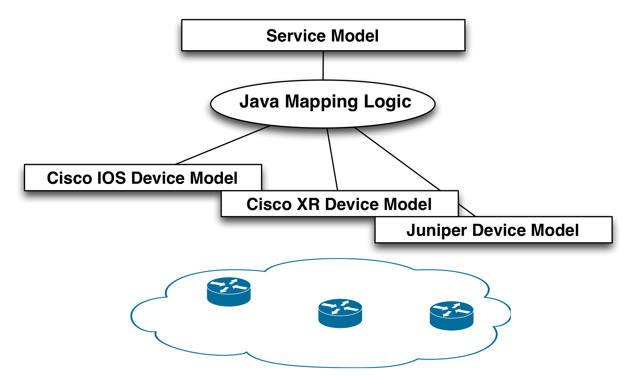
This strategy has some drawbacks:
-
Managing different device vendors. If we would introduce more vendors in the network this would need to be handled by the Java code. Of course this can be factored into separate classes in order to keep the general logic clean and just passing the device details to specific vendor classes, but this gets complex and will always require Java programmers for introducing new device types.
-
No clear separation of concerns, domain expertise. The general business logic for a service is one thing, detailed configuration knowledge of device types something else. The latter requires network engineers and the first category is normally separated into a separate team that deals with OSS integration.
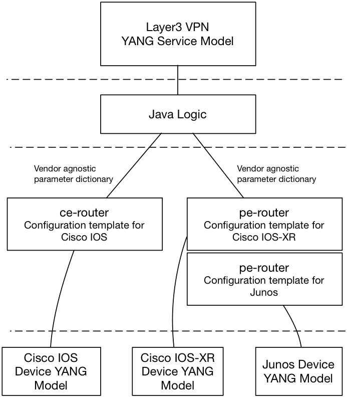
Java and templates can be combined:
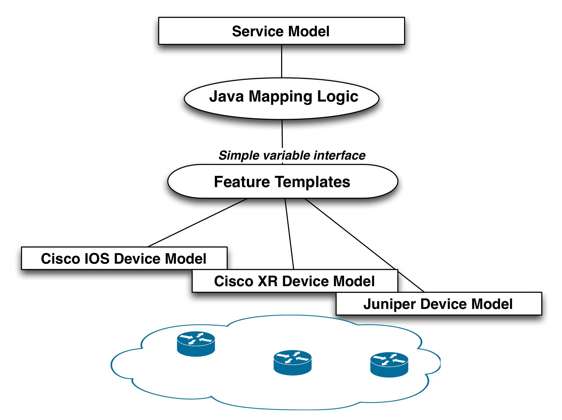
In this model the Java layer focuses on required logic, but it never
touches concrete device models from various vendors. The vendor
specific details are abstracted away using feature templates. The
templates take variables as input from the service logic, and the
templates in turn transform these into concrete device
configuration. Introduction of a new device type does not affect the
Java mapping.
This approach has several benefits:
-
The service logic can be developed independently of device types.
-
New device types can be introduced at runtime without affecting service logic.
-
Separation of concerns: network engineers are comfortable with templates, they look like a configuration snippet. They have the expertise how configuration is applied to real devices. People defining the service logic often are more programmers, they need to interface with other systems etc, this suites a Java layer.
Note that the logic layer does not understand the device types, the templates will dynamically apply the correct leg of the template depending on which device is touched.
From an abstraction point of view we want a template that takes the following variables:
-
VLAN id
-
Device and interface
So the mapping logic can just pass these variables to the feature template and it will apply it to a multi-vendor network.
Create a template as described before.
-
Create a concrete configuration on a device, or several devices of different type
-
Request NSO to display that as XML
-
Replace values with variables
This results in a feature template like below:
<!-- Feature Parameters -->
<!-- $DEVICE -->
<!-- $VLAN_ID -->
<!-- $INTF_NAME -->

<config-template xmlns="http://tail-f.com/ns/config/1.0"
                 servicepoint="vlan">
  <devices xmlns="http://tail-f.com/ns/ncs">
    <device>
      <name>{$DEVICE}</name>
      <config>
        <vlan xmlns="urn:ios" tags="merge">
          <vlan-list>
            <id>{$VLAN_ID}</id>
          </vlan-list>
        </vlan>
        <interface xmlns="urn:ios" tags="merge">
          <FastEthernet tags="nocreate">
            <name>{$INTF_NAME}</name>
            <switchport>
              <trunk>
                <allowed>
                  <vlan tags="merge">
                    <vlans>{$VLAN_ID}</vlans>
                  </vlan>
                </allowed>
              </trunk>
            </switchport>
          </FastEthernet>
        </interface>
      </config>
    </device>
  </devices>
</config-template>
This template only maps to Cisco IOS devices (the xmlns="urn:ios" namespace), but you can add "legs" for other device types at any point in time and reload the package.
Note
Nodes set with a template variable evaluating to the empty string are ignored, e.g., the setting <some-tag>{$VAR}</some-tag> is ignored if the template variable $VAR evaluates to the empty string. However, this does not apply to XPath expressions evaluating to the empty string. A template variable can be surrounded by the XPath function string() if it is desirable to set a node to the empty string.
The Java mapping logic for applying the template is shown below:
Note that the Java code has no clue about the underlying device
type, it just passes the feature variables to the template. At
run-time you can update the template with mapping to other device
types. The Java-code stays untouched, if you modify an existing
VLAN service instance to refer to the new device type the
commit will generate the corresponding configuration
for that device.
The smart reader will complain, "why do we have the Java layer at all?", this could have been done as a pure template solution. That is true, but now this simple Java layer gives room for arbitrary complex service logic before applying the template.
The steps to build the solution described in this section are:
-
Create a run-time directory: $ mkdir ~/service-template; cd ~/service-template
-
Generate a netsim environment: $ ncs-netsim create-network $NCS_DIR/packages/neds/cisco-ios 3 c
-
Generate the NSO runtime environment: $ ncs-setup --netsim-dir ./netsim --dest ./
-
Create the VLAN package in the packages directory: $ cd packages; ncs-make-package --service-skeleton java vlan
-
Create a template directory in the VLAN package: $ cd vlan; mkdir templates
-
Save the above described template in
packages/vlan/templates -
Create the YANG service model according to above:
packages/vlan/src/yang/vlan.yang -
Update the Java code according to above:
packages/vlan/src/java/src/com/example/vlan/vlanRFS.java -
Build the package: in
packages/vlan/srcdomake -
Start NSO
This service shows a more elaborate service mapping. It is based on the
examples.ncs/service-provider/mpls-vpn example.
MPLS VPNs are a type of a Virtual Private Network (VPN) that achieves segmentation of network traffic using Multiprotocol Label Switching (MPLS), often found in Service Provider (SP) networks. The Layer 3 variant uses BGP to connect and distribute routes between sites of the VPN.
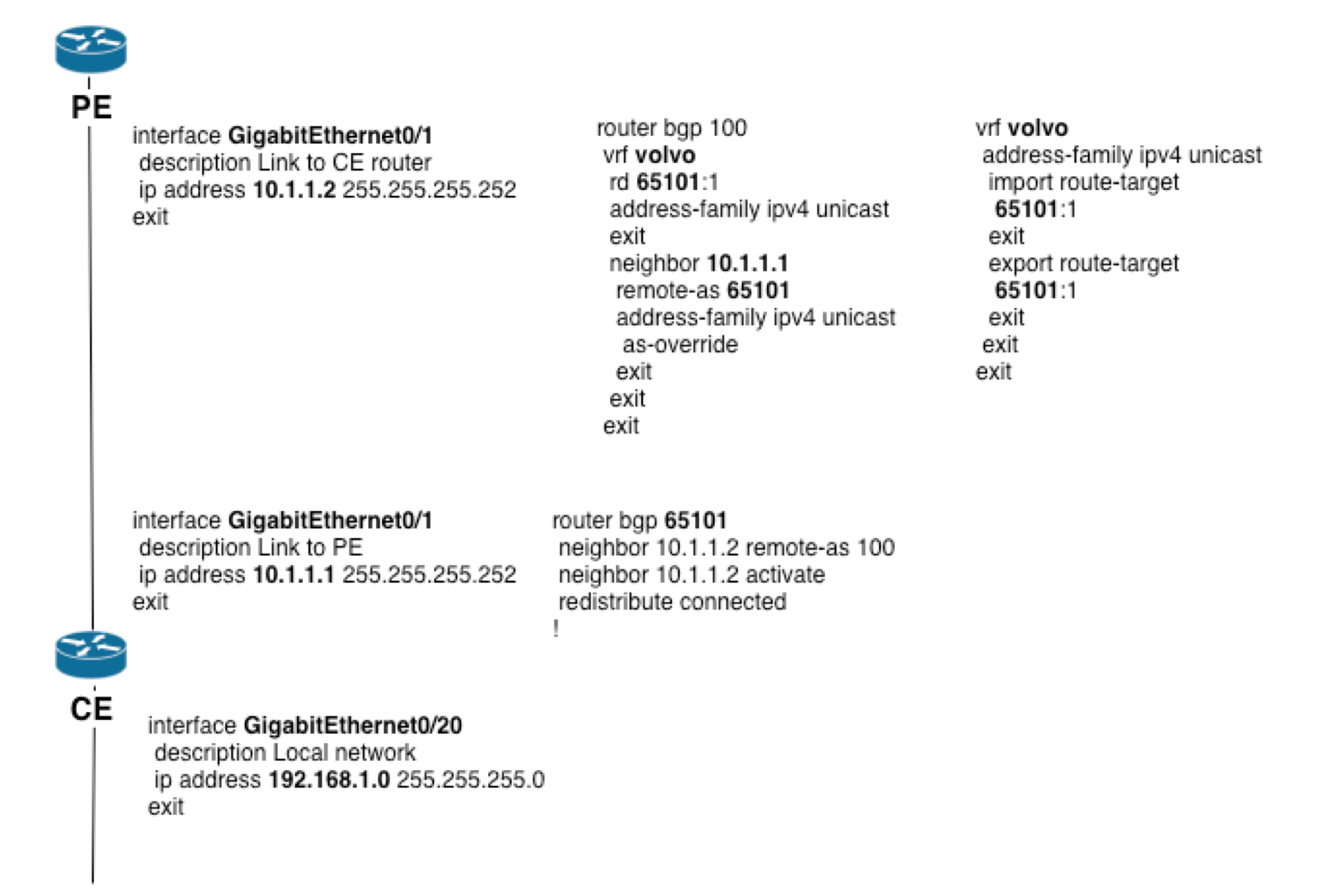
The figure below illustrates an example configuration for one leg of the VPN. Configuration items in bold are variables that are generated from the service inputs.
Sometimes the input parameters are enough to generate the corresponding device configurations. But in many cases this is not enough. The service mapping logic may need to reach out to other data in order to generate the device configuration. This is common in the following scenarios:
-
Policies: it might make sense to define policies that can be shared between service instances. The policies, for example QoS, have data models of their own (not service models) and the mapping code reads from that.
-
Topology information: the service mapping might need to know connected devices, like which PE the CE is connected to.
-
Resources like VLAN IDs, IP addresses: these might not be given as input parameters. This can be modeled separately in NSO or fetched from an external system.
It is important to design the service model to consider the above examples: what is input? what is available from other sources? This example illustrates how to define QoS policies "on the side". A reference to an existing QoS policy is passed as input. This is a much better principle than giving all QoS parameters to every service instance. Note well that if you modify the QoS definitions that services are referring to, this will not change the existing services. In order to have the service to read the changed policies you need to perform a re-deploy on the service.
This example also uses a list that maps every CE to a PE. This list needs to be populated before any service is created. The service model only has the CE as input parameter, and the service mapping code performs a lookup in this list to get the PE. If the underlying topology changes a service re-deploy will adopt the service to the changed CE-PE links. See more on topology below.
NSO has a package to manage resources like VLAN and IP addresses as a pool within NSO. In this way the resources are managed within the transaction. The mapping code could also reach out externally to get resources. Nano services are recommended for this.
Using topology information in the instantiation of a NSO service is a common approach, but also an area with many misconceptions. Just like a service in NSO takes a black-box view of the configuration needed for that service in the network NSO treats topologies in the same way. It is of course common that you need to reference topology information in the service but it is highly desirable to have a decoupled and self-sufficient service that only uses the part of the topology that is interesting/needed for the specific service should be used.
Other parts of the topology could either be handled by other services or just let the network state sort it out, it does not necessarily relate to configuration the network. A routing protocol will for example handle the IP path through the network.
It is highly desirable to not introduce unneeded dependencies towards network topologies in your service.
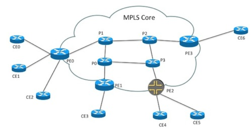
To illustrate this, lets look at a Layer 3 MPLS VPN service. A logical overview of an MPLS VPN with three endpoints could look something like this. CE routers connecting to PE routers, that are connected to an MPLS core network. In the MPLS core network there are a number of P routers.
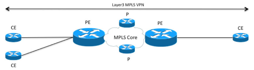
In the service model you only want to configure the CE devices to use as endpoints. In this case topology information could be used to sort out what PE router each CE router is connected to. However, what type of topology do you need? Lets look at a more detailed picture of what the L1 and L2 topology could look like for one side of the picture above.
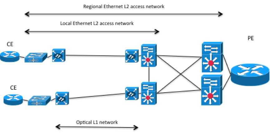
In pretty much all networks there is an access network between the CE and PE router. In the picture above the CE routers are connected to local Ethernet switches connected to a local Ethernet access network, connected through optical equipment. The local Ethernet access network is connected to a regional Ethernet access network, connected to the PE router. Most likely the physical connections between the devices in this picture has been simplified, in the real world redundant cabling would be used. The example above is of course only one example of how an access network could look like and it is very likely that a service provider have different access technologies. For example Ethernet, ATM, or a DSL based access network.
Depending on how you design the L3VPN service, the physical cabling or the exact traffic path taken in the layer 2 Ethernet access network might not be that interesting, just like we don't make any assumptions or care about how traffic is transported over the MPLS core network. In both these cases we trust the underlying protocols handling state in the network, spanning tree in the Ethernet access network, and routing protocols like BGP in the MPLS cloud. Instead in this case it could make more sense to have a separate NSO service for the access network, both so it can be reused for both for example L3VPN's and L2VPN's but also to not tightly couple to the access network with the L3VPN service since it can be different (Ethernet or ATM etc.).
Looking at the topology again from the L3VPN service perspective, if services assume that the access network is already provisioned or taken care of by another service, it could look like this.
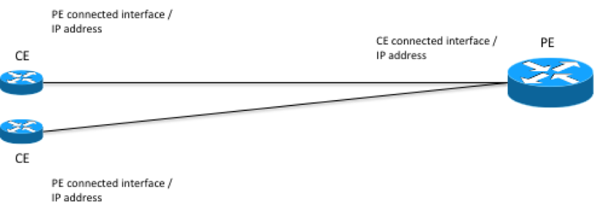
The information needed to sort out what PE router a CE router is connected to as well as configuring both CE and PE routers is:
-
Interface on the CE router that is connected to the PE router, and IP address of that interface.
-
Interface on the PE router that is connected to the CE router, and IP address to the interface.
This section describes the creation of a MPLS L3VPN service in a
multi vendor environment applying the concepts described above.
The example discussed can be found in
examples.ncs/service-provider/mpls-vpn. The
example network consists of Cisco ASR 9k and Juniper core routers
(P and PE) and Cisco IOS based CE routers.
The goal with the NSO service is to setup a MPLS Layer3 VPN on a number of CE router endpoints using BGP as the CE-PE routing protocol. Connectivity between the CE and PE routers is done through a Layer2 Ethernet access network, which is out of scope for this service. In a real world scenario the access network could for example be handled by another service.
In the example network we can also assume that the MPLS core network already exists and is configured.
When designing service YANG models there are a number of things to take into consideration. The process usually involves the following steps:
-
Identify the resulting device configurations for a deployed service instance.
-
Identify what parameters from the device configurations that are common and should be put in the service model.
-
Ensure that the scope of the service and the structure of the model works with the NSO architecture and service mapping concepts. For example, avoid unnecessary complexities in the code to work with the service parameters.
-
Ensure that the model is structured in a way so that integration with other systems north of NSO works well. For example, ensure that the parameters in the service model map to the needed parameters from an ordering system.
Step 1 and 2: Device Configurations and Identifying parameters
Deploying a MPLS VPN in the network results in the following basic CE and PE configurations. The snippets below only include the Cisco IOS and Cisco IOS-XR configurations. In a real process all applicable device vendor configurations should be analyzed.
interfaceGigabitEthernet0/1.77descriptionLink to PE / pe0 - GigabitEthernet0/0/0/3encapsulation dot1Q77ip address192.168.1.5 255.255.255.252service-policy outputvolvo! policy-mapvolvoclass class-default shape average6000000! ! interfaceGigabitEthernet0/11descriptionvolvo local networkip address10.7.7.1 255.255.255.0exit router bgp65101neighbor192.168.1.6 remote-as 100neighbor192.168.1.6 activatenetwork10.7.7.0!
  vrf volvo
   address-family ipv4 unicast
    import route-target
     65101:1
    exit
    export route-target
     65101:1
    exit
   exit
  exit
  policy-map volvo-ce1
   class class-default
    shape average 6000000 bps
   !
   end-policy-map
  !
  interface GigabitEthernet 0/0/0/3.77
   description Link to CE / ce1 - GigabitEthernet0/1
   ipv4 address 192.168.1.6 255.255.255.252
   service-policy output volvo-ce1
   vrf         volvo
   encapsulation dot1q 77
  exit
  router bgp 100
   vrf volvo
    rd 65101:1
    address-family ipv4 unicast
    exit
    neighbor 192.168.1.5
     remote-as 65101
     address-family ipv4 unicast
      as-override
     exit
    exit
   exit
  exit
The device configuration parameters that need to be uniquely
configured for each VPN have been marked in bold.
Step 3 and 4: Model Structure and Integration with other Systems
When configuring a new MPLS l3vpn in the network we will have to configure all CE routers that should be interconnected by the VPN, as well as the PE routers they connect to.
However when creating a new l3vpn service instance in NSO it would be ideal if only the endpoints (CE routers) are needed as parameters to avoid having knowledge about PE routers in a northbound order management system. This means a way to use topology information is needed to derive or compute what PE router a CE router is connected to. This makes the input parameters for a new service instance very simple. It also makes the entire service very flexible, since we can move CE and PE routers around, without modifying the service configuration.
Resulting YANG Service Model:
container vpn {

  list l3vpn {
    tailf:info "Layer3 VPN";

    uses ncs:service-data;
    ncs:servicepoint l3vpn-servicepoint;

    key name;
    leaf name {
      tailf:info "Unique service id";
      type string;
    }
    leaf as-number {
      tailf:info "MPLS VPN AS number.";
      mandatory true;
      type uint32;
    }

    list endpoint {
      key id;
      leaf id {
        tailf:info "Endpoint identifier";
        type string;
      }
      leaf ce-device {
         mandatory true;
         type leafref {
           path "/ncs:devices/ncs:device/ncs:name";
         }
      }
      leaf ce-interface {
        mandatory true;
        type string;
      }
      leaf ip-network {
        tailf:info “private IP network”;
        mandatory true;
        type inet:ip-prefix;
      }
      leaf bandwidth {
        tailf:info "Bandwidth in bps";
        mandatory true;
        type uint32;
      }
    }
  }
}
The snipped above contains the l3vpn service model. The structure of the model is very simple. Every VPN has a name, an as-number and a list of all the endpoints in the VPN. Each endpoint has:
-
A unique id
-
A reference to a device (a CE router in our case)
-
A pointer to the LAN local interface on the CE router. This is kept as a string since we want this to work in a multi-vendor environment.
-
LAN private IP network
-
Bandwidth on the VPN connection.
To be able to derive the CE to PE connections we use a very simple topology model. Notice that this YANG snippet does not contain any servicepoint, which means that this is not a service model but rather just a YANG schema letting us store information in CDB.
container topology {
  list connection {
    key name;
    leaf name {
      type string;
    }
    container endpoint-1 {
      tailf:cli-compact-syntax;
      uses connection-grouping;
    }
    container endpoint-2 {
      tailf:cli-compact-syntax;
      uses connection-grouping;
    }
    leaf link-vlan {
      type uint32;
    }
  }
}

grouping connection-grouping {
  leaf device {
    type leafref {
      path "/ncs:devices/ncs:device/ncs:name";
    }
  }
  leaf interface {
    type string;
  }
  leaf ip-address {
    type tailf:ipv4-address-and-prefix-length;
  }
}
The model basically contains a list of connections, where each connection points out the device, interface and ip-address in each of the connection.
Since we need to lookup which PE routers to configure using the topology model in the mapping logic it is not possible to use a declarative configuration template based mapping. Using Java and configuration templates together is the right approach.
The Java logic lets you set a list of parameters that can be consumed by the configuration templates. One huge benefit of this approach is that all the parameters set in the Java code is completely vendor agnostic. When writing the code there is no need for knowledge of what kind of devices or vendors that exists in the network, thus creating an abstraction of vendor specific configuration. This also means that in to create the configuration template there is no need to have knowledge of the service logic in the Java code. The configuration template can instead be created and maintained by subject matter experts, the network engineers.
With this service mapping approach it makes sense to modularize the service mapping by creating configuration templates on a per feature level, creating an abstraction for a feature in the network. In this example means we will create the following templates:
-
CE router
-
PE router
This is both to make services easier to maintain and create but also to create components that are reusable from different services. This can of course be even more detailed with templates with for example BGP or interface configuration if needed.
Since the configuration templates are decoupled from the service logic it is also possible to create and add additional templates in a running NSO system. You can for example add a CE router from a new vendor to the layer3 VPN service by only creating a new configuration template, using the set of parameters from the service logic, to a running NSO system without changing anything in the other logical layers.
The Java code part for the service mapping is very simple and follows the following pseudo code steps:
READ topology
FOR EACH endpoint
        USING topology
DERIVE connected-pe-router
                READ ce-pe-connection
        SET pe-parameters
        SET ce-parameters
        APPLY TEMPLATE l3vpn-ce
        APPLY TEMPLATE l3vpn-pe
This section will go through relevant parts of the Java outlined by the pseudo code above. The code starts with defining the configuration templates and reading the list of endpoints configured and the topology. The Navu API is used for navigating the data models.
Template peTemplate = new Template(context, "l3vpn-pe");
        Template ceTemplate = new Template(context,"l3vpn-ce");
        NavuList endpoints = service.list("endpoint");
        NavuContainer topology = ncsRoot.getParent().
                container("http://com/example/l3vpn").
                container("topology");
The next step is iterating over the VPN endpoints configured in the service, find out connected PE router using small helper methods navigating the configured topology.
 for(NavuContainer endpoint : endpoints.elements()) {
            try {
                String ceName =  endpoint.leaf("ce-device").valueAsString();
                // Get the PE connection for this endpoint router
                NavuContainer conn =
                    getConnection(topology,
                                  endpoint.leaf("ce-device").valueAsString());
                NavuContainer peEndpoint = getConnectedEndpoint(
                                                conn,ceName);
                NavuContainer ceEndpoint = getMyEndpoint(
                                                conn,ceName);
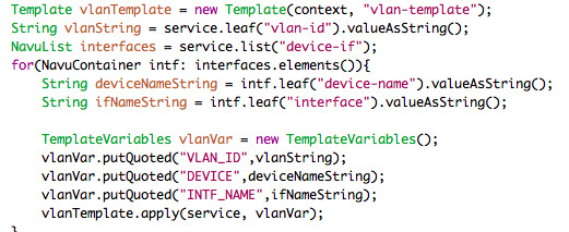
The parameter dictionary is created from the TemplateVariables class and is populated with appropriate parameters.
TemplateVariables vpnVar = new TemplateVariables();
vpnVar.putQuoted("PE",peEndpoint.leaf("device").valueAsString());
vpnVar.putQuoted("CE",endpoint.leaf("ce-device").valueAsString());
vpnVar.putQuoted("VLAN_ID", vlan.valueAsString());
vpnVar.putQuoted("LINK_PE_ADR",
getIPAddress(peEndpoint.leaf("ip-address").valueAsString()));
vpnVar.putQuoted("LINK_CE_ADR",
                getIPAddress(ceEndpoint. leaf("ip-address").valueAsString()));
vpnVar.putQuoted("LINK_MASK",
                getNetMask(ceEndpoint. leaf("ip-address").valueAsString()));
vpnVar.putQuoted("LINK_PREFIX",
                getIPPrefix(ceEndpoint.leaf("ip-address").valueAsString()));
The last step after all parameters have been set is applying the templates for the CE and PE routers for this VPN endpoint.
peTemplate.apply(service, vpnVar);
ceTemplate.apply(service, vpnVar);
The configuration templates are XML templates based on the structure of device YANG models.There is a very easy way to create the configuration templates for the service mapping if NSO is connected to a device with the appropriate configuration on it, using the following steps.
-
Configure the device with the appropriate configuration.
-
Add the device to NSO
-
Sync the configuration to NSO.
-
Display the device configuration in XML format.
-
Save the XML output to a configuration template file and replace configured values with parameters
The commands in NSO give the following output. To make the example simpler only the BGP part of the configuration is used
admin@ncs#devices device ce1 sync-fromadmin@ncs#show running-config devices device ce1 config \ ios:router bgp | display xml<config xmlns="http://tail-f.com/ns/config/1.0"> <devices xmlns="http://tail-f.com/ns/ncs"> <device> <name>ce1</name> <config> <router xmlns="urn:ios"> <bgp> <as-no>65101</as-no> <neighbor> <id>192.168.1.6</id> <remote-as>100</remote-as> <activate/> </neighbor> <network> <number>10.7.7.0</number> </network> </bgp> </router> </config> </device> </devices> </config>
The final configuration template with the replaced parameters marked in bold is shown below. If the parameter starts with a $-sign is taken from the Java parameter dictionary, otherwise it is a direct xpath reference to the value from the service instance.
<config-template xmlns="http://tail-f.com/ns/config/1.0">
  <devices xmlns="http://tail-f.com/ns/ncs">
    <device tags="nocreate">
      <name>{$CE}</name>
      <config>
       <router xmlns="urn:ios" tags="merge">
          <bgp>
            <as-no>{/as-number}</as-no>
            <neighbor>
              <id>{$LINK_PE_ADR}</id>
              <remote-as>100</remote-as>
              <activate/>
            </neighbor>
            <network>
              <number>{$LOCAL_CE_NET}</number>
            </network>
          </bgp>
        </router>
      </config>
    </device>
  </devices>
</config-template>