Hub and Spoke Topology
Cisco Catalysts SD-WAN Fabric by default creates a full-mesh topology between all WAN-Edge routers. By using Policies on the Manager, we can establish different topologies (like Hub and Spoke) per segment and create flows as per the design requirements.
There are multiple ways that you can create a Hub-and-Spoke topology for sites with single or multiple VPNs. Here are three different ways to create a Hub and Spoke topology in the network.
- Hub-and-Spoke Topology Policy
- Custom Control Topology Policy
Pre-Check
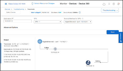
By default, the traceroute shows that the topology between three sites (Site1, Site2, and Site3) is full mesh, where each site can directly reach the other sites.
- Login to Cisco Catalyst SD-WAN Manager, go to Monitor > Devices, click on Site1-cEdge01 site.
- On the left side, scroll to the bottom and click on Troubleshooting option then Trace Route.
Hub and Spoke Topology Policy
Traceroute from Site1-cEdge01 VPN1 interface to a host 10.10.22.12 (Site2-cEdge01 VPN1)
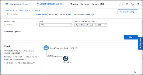
Traceroute from Site2-cEdge01 VPN1 interface to Site1-cEdge01 VPN1 interface shows direct data-tunnel.
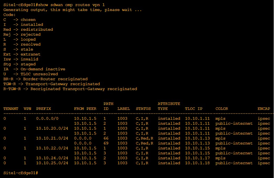
OMP routing table on Site1-cEdge01 shows that Site1-cEdge01 learns subnet 10.10.21.0/24 from TLOC 10.10.1.13.
Hub-and-Spoke Topology Policy
This policy filters advertisements of routes and TLOCs between the spokes. Therefore, a DC site must advertise a default route to the spoke sites to facilitate routing between spokes.
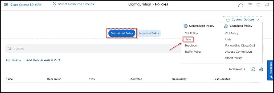
- Go to Cisco Catalyst SD-WAN Manager > Configuration > Policies > Centralized Policy > Customer Options Click Lists under Centralized Policy.
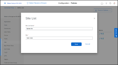
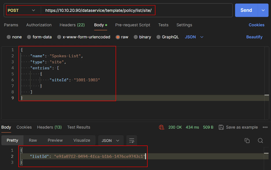
- Create Spokes Site List.
- Click Site > New Site List
- Enter Site List Name and Site IDs, then click Save.
REST API
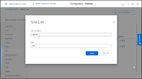
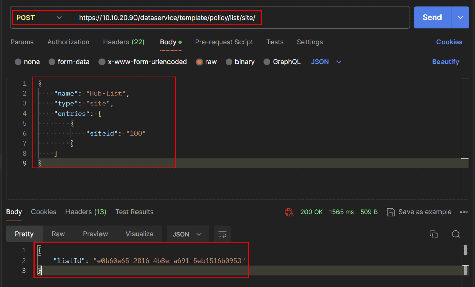
- Similarly create Hub Site List.
-Click Site > New Site List -Enter Site List Name and Site IDs, then click Save.
REST API
- Get Site List IDs for Spokes and Hub.
REST API
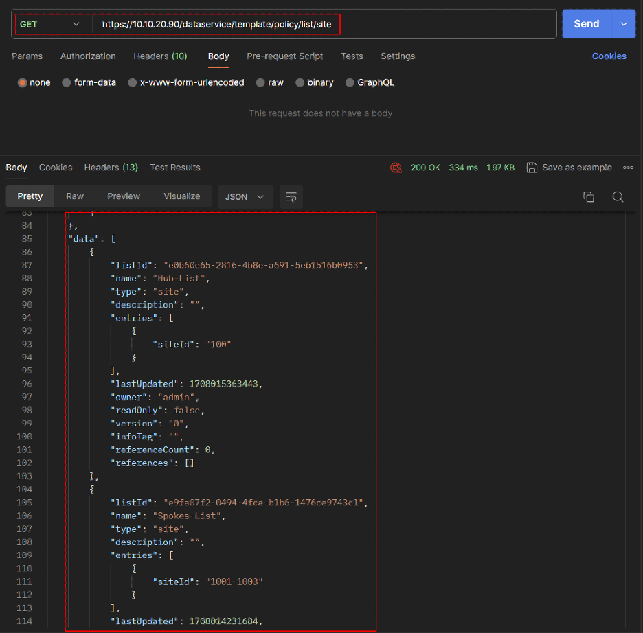
REST API
VPN List allows us to create separate topologies per VPN.
- Create VPN List for VPN 1.
- Click VPN > New VPN List
- Enter VPN List Name and VPN number, then click Save.
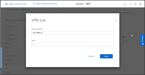
REST API
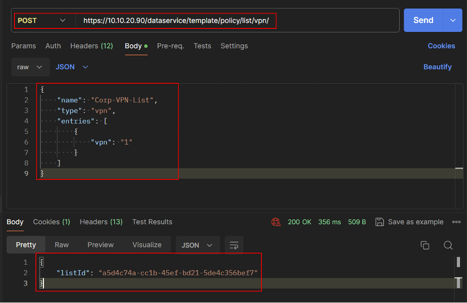
- Get the VPN List ID.
REST API
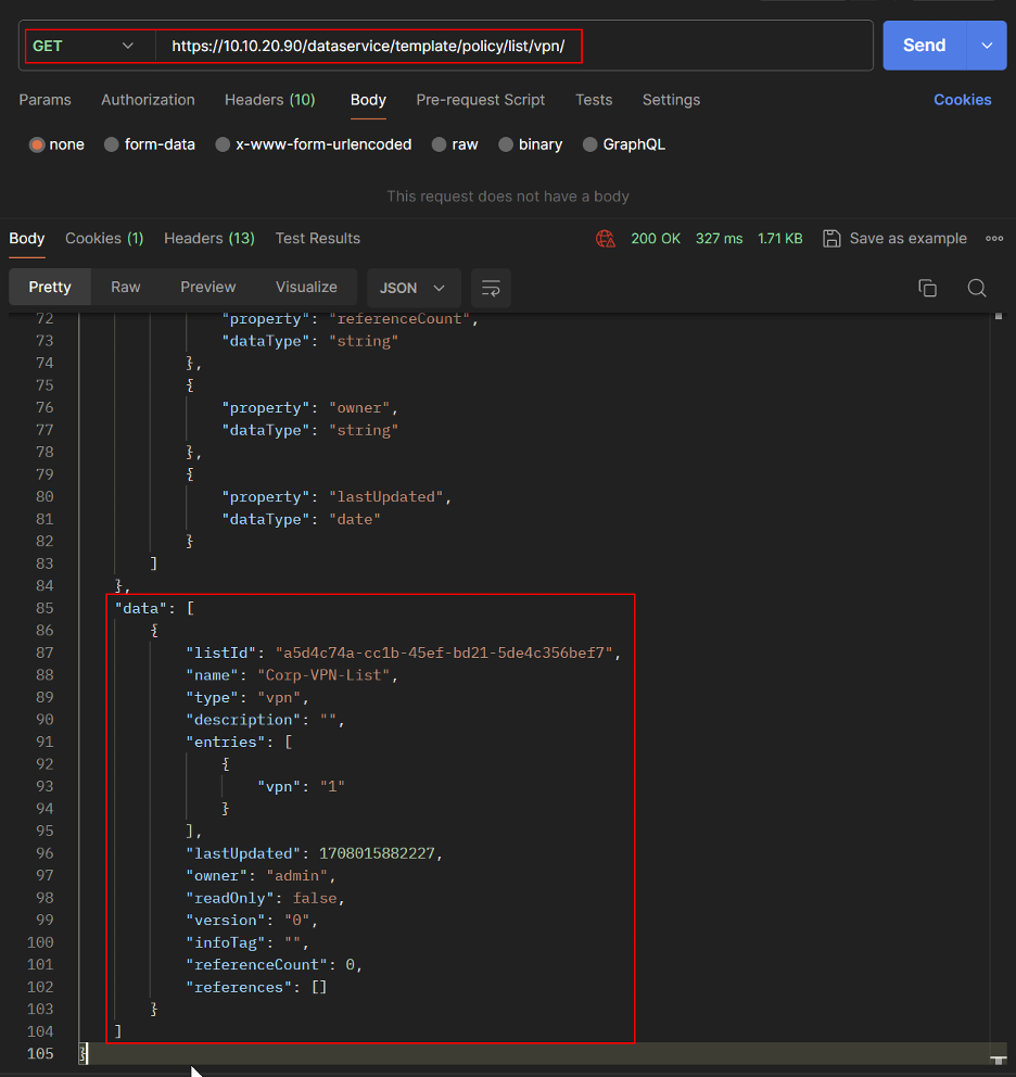
- Create Hub and Spoke Topology.
Go to Cisco Catalyst SD-WAN Manager > Configuration > Policies > Custom Options.
Click Topology under Centralized Policy
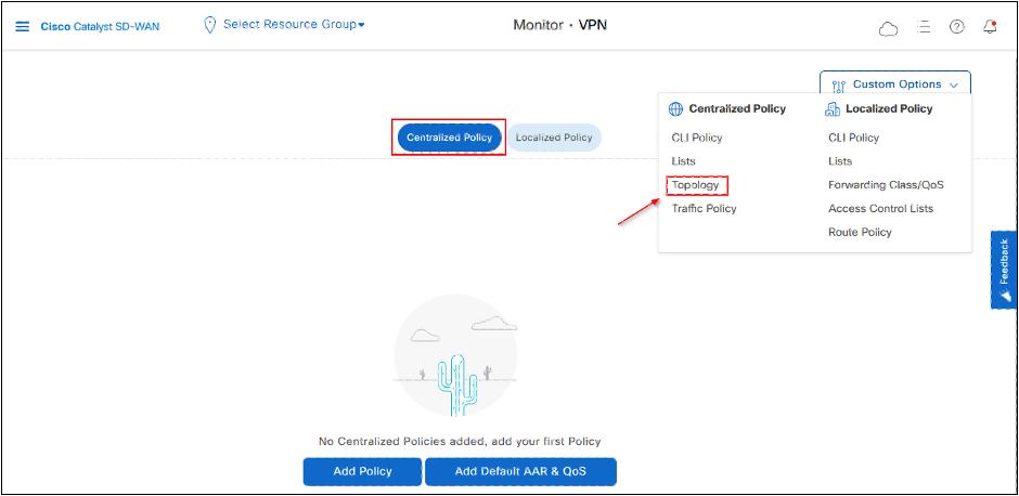
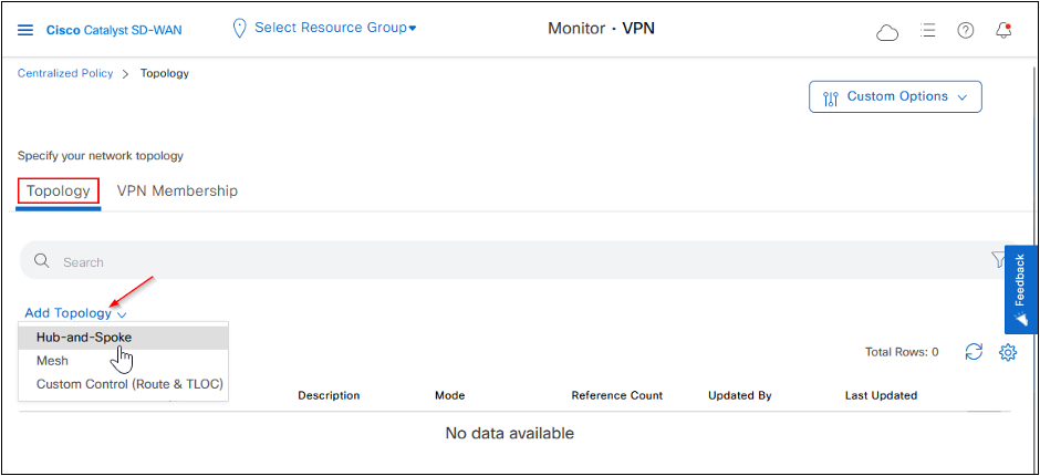
- Click Add Topology then click on Hub-and-Spoke.
Fill the Name and Description fields, add VPN List, Spoke, and Hub Site Lists.
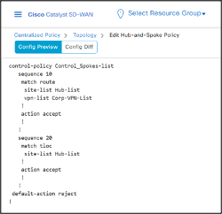
Click Preview on the left bottom side to see the CLI of the Policy before saving.
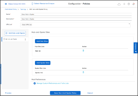
- Save the Policy by clicking Save Hub-And-Spoke Policy.
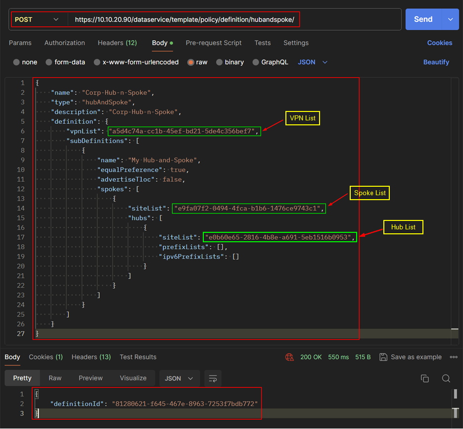
REST API
Create Hub and Spoke Topology Policy.
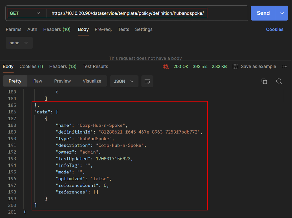
- Get the List of Topology Policy.
REST API
- Let’s add this Topology Policy in the list of Centralized Policy.
Go to Cisco Catalyst SD-WAN Manager > Configuration > Policies > Centralized Policy.
Click Add Policy, then click Next.
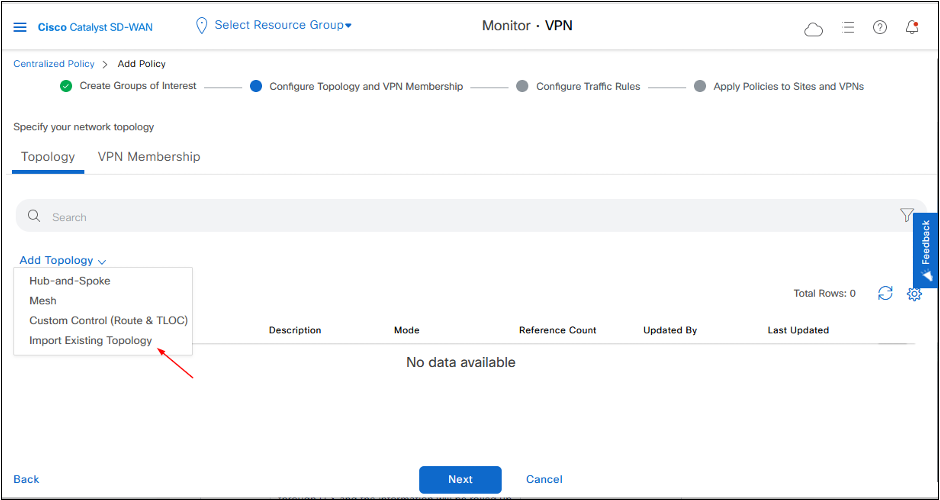
Under Configure Topology and VPN Membership, click Add Topology to add choose Import Existing Topology option.
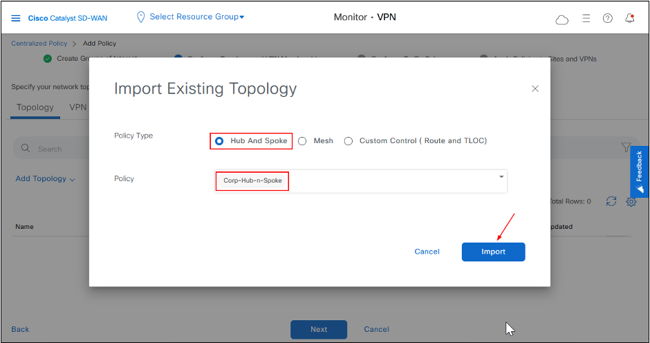
- Select the Policy from the drop-down, then click Import.
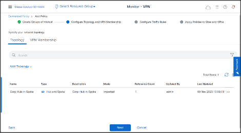
- Click Next > Next, fill the Policy Name and Description.
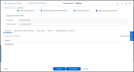
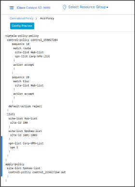
- Click Preview to view the complete Policy in CLI.
As the CLI shows, once you activate the policy, the system pushes it to all controllers, which implement it in OUT direction to the spokes.
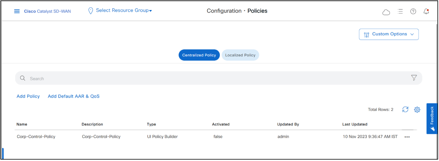
- Click Save Policy.
REST API
Create Centralized Policy.
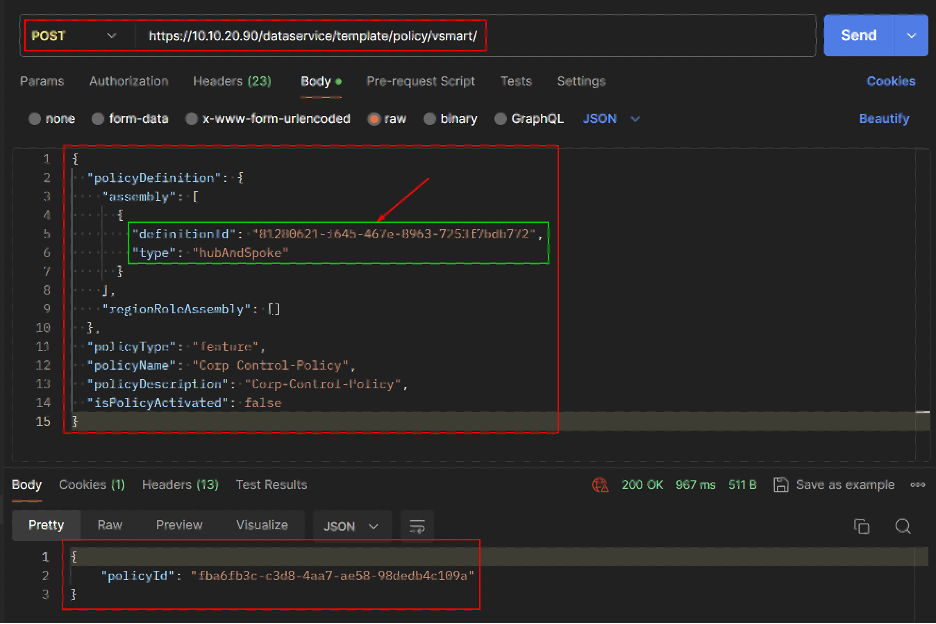
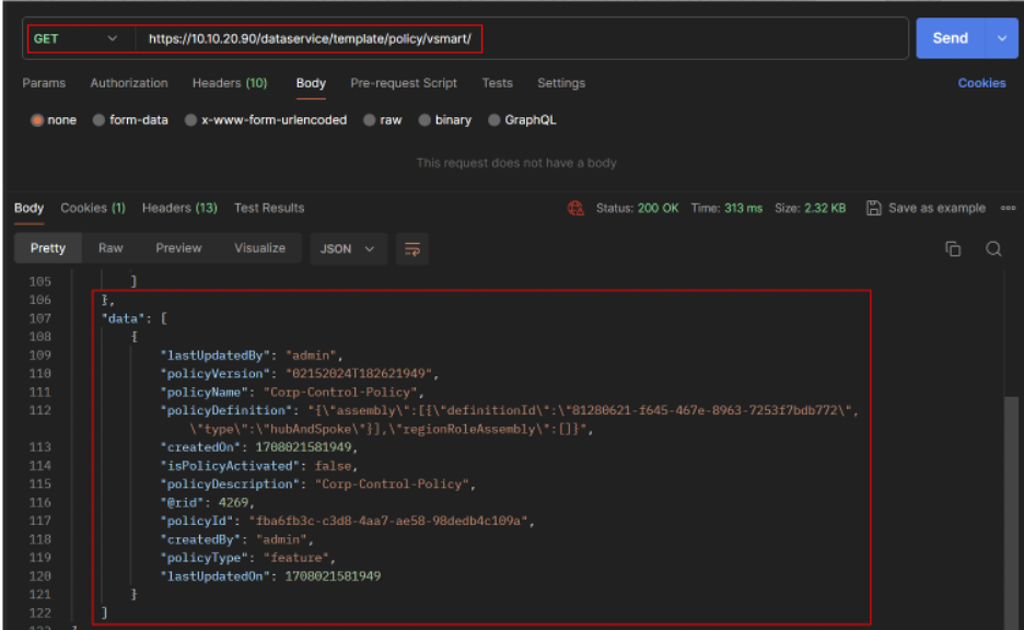
- Get the Centralized Policy details.
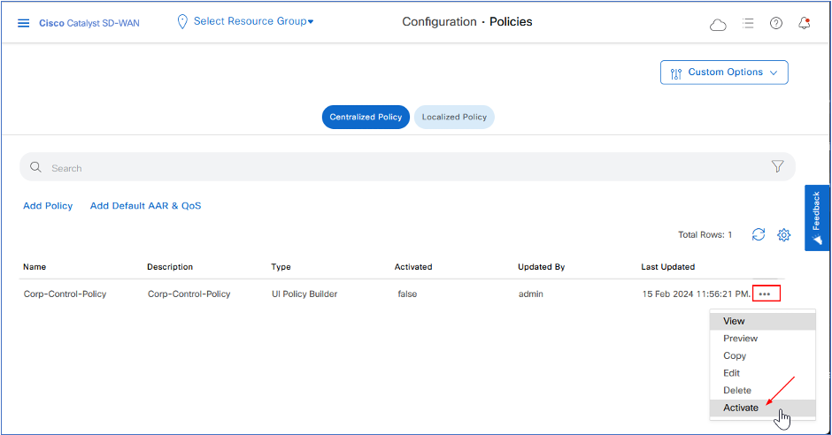
- Activate the policy by clicking “…” of Hub-and-Spoke Policy and then click Activate.
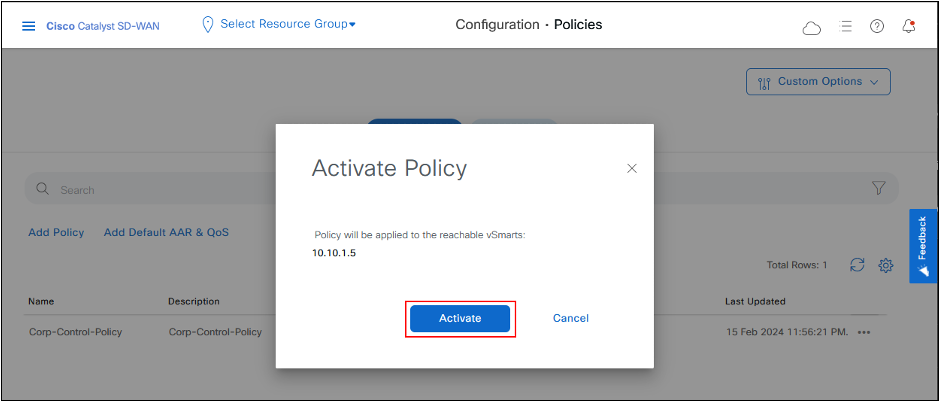
- Click Activate again.
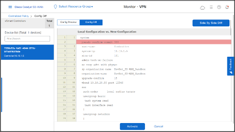
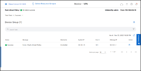
- Hub-and-Spoke Policy is successfully pushed to the Cisco Catalyst SD-WAN Controller.
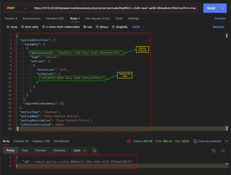
REST API Active Policy.
Verification/Testing
On Site1-cEdge01, OMP routing table shows that it is not learning any routes from Site2.
Traceroute from Site1-cEdge01 VPN1 interface to a host 10.10.22.12 (Site2-cEdge01 VPN1) takes the default route that the DC site advertises.
Deactivate the policy when not needed.
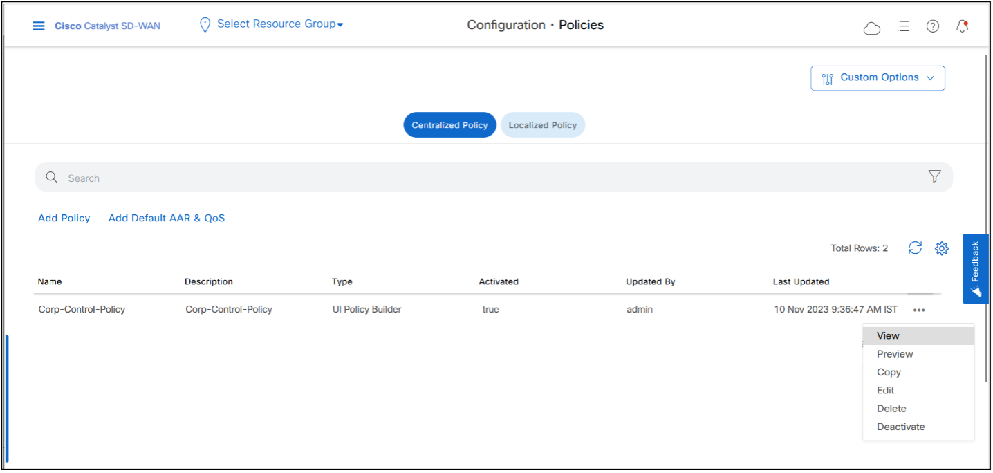
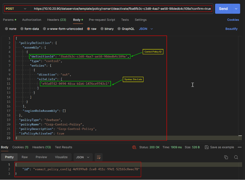
REST API
Deactivate Policy.
Custom Control Topology Policy
You can also use Centralized Custom Control Policy to create a Hub and Spoke topology. In this policy, we’ll change the next hop TLOC address for the OMP routes of spokes to the hub’s TLOC before the controller advertises routes to other spokes.
To start a new policy:
- Go to Cisco Catalyst SD-WAN Manager > Configuration > Policies > Centralized Policy > Add Policy.
We have already created Site Lists and VPN List in the previous section of Hub-and-Spoke Topology Policy. (Create Site List for Spokes and Hub if not created already.)
For guidance, refer to the previous section in this document.
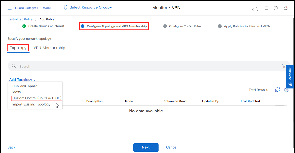
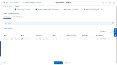
-Click Next to go to Configure Topology and VPN Membership, click Add Topology > Custom Control (Route & TLOC)
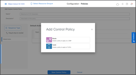
-Click Sequence Type and then click Route.
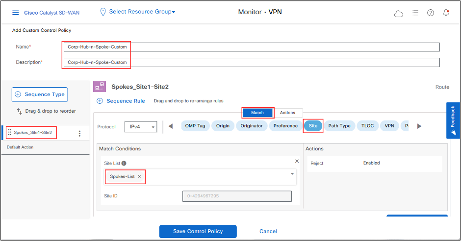
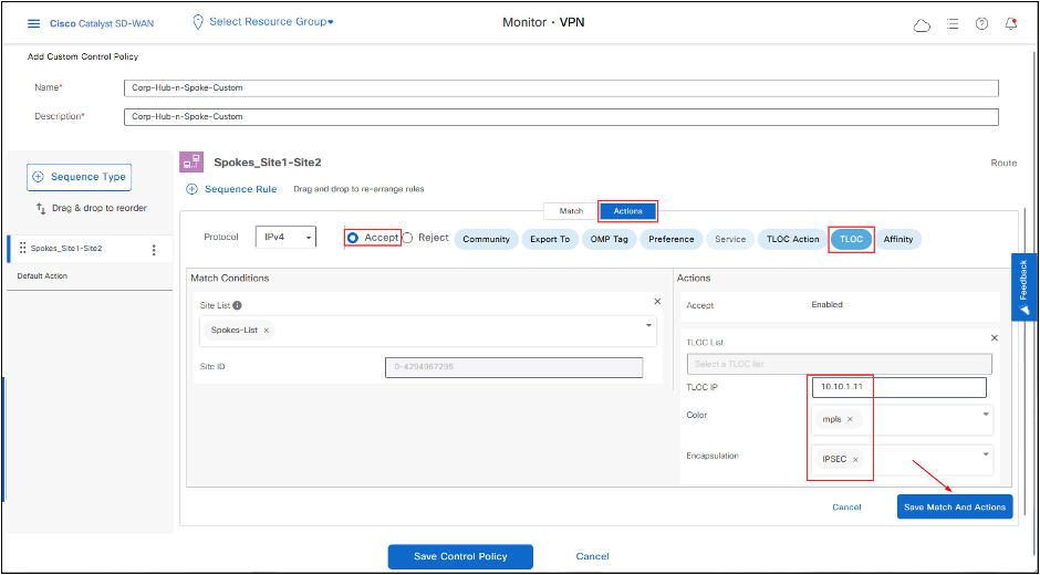
-Add a Name and Description, click Sequence Rule, also rename the Rule Sequence. -Match on Site and select the Site List for Spokes.
-Change Action for the rule to Accept and set the TLOC to DC-cEdge01 TLOC IP, color to MPLS and encapsulation to IPSEC. This action changes the next-hop TLOC IP of the prefixes that the spokes advertise to DC-cEdge01 TLOC. (To specify more than one TLOC that you can use as a next hop, use TLOC List. You can set Color and Encapsulation to different values if needed).
- Click Save Match And Actions to save to rule.
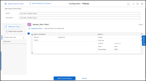
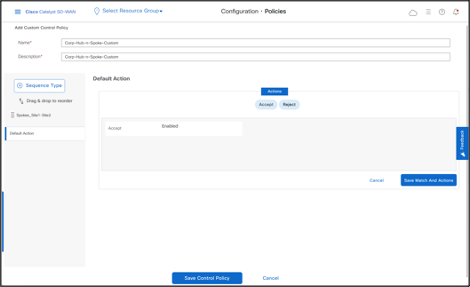
Change the Default Action to Accept, then click Save Match And Actions.
Click Save Control Policy.
- Click Next > Next.
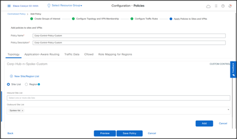
- In Apply Policies to Sites and VPNs section, add Policy Name, Policy Description. -Click New Site/Region List and then add Site List of Spokes in Outbound direction.
Outbound direction is from the controller perspective because the controller is the control plane that receives prefixes from all branches and then advertises them to other sites. This policy applies in outbound direction, which means that the controller updates the TLOC of Site1 prefixes before the controller advertises them to Site2.
- Click Add.
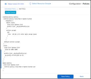
- Click Preview to see the policy details in CLI. The CLI of the policy is below.
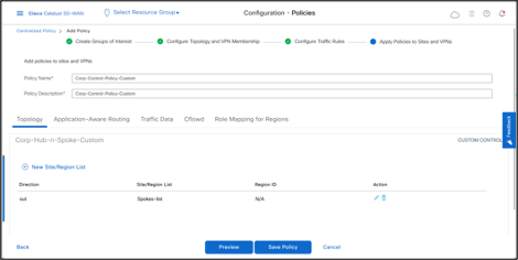
- Click Save Policy
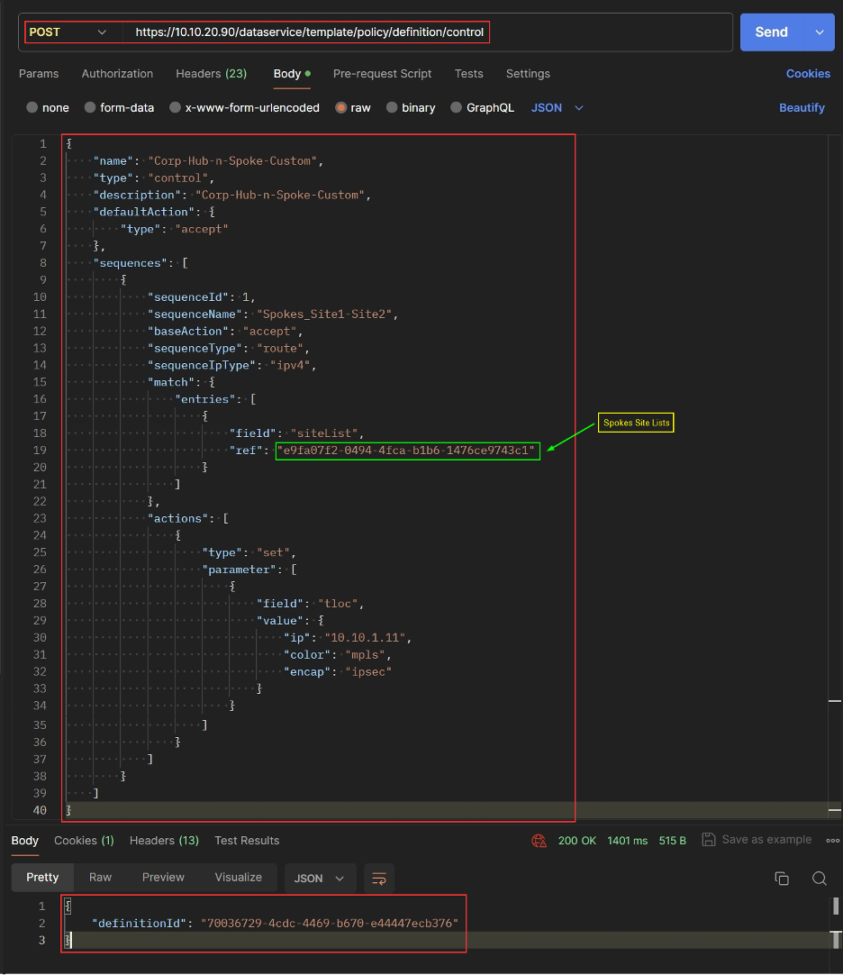
REST API
Create Custom Control Topology
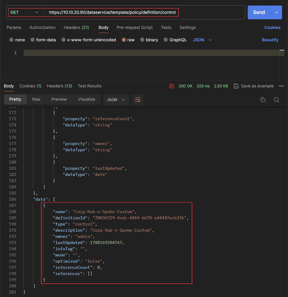
Get Custom Control Topology List
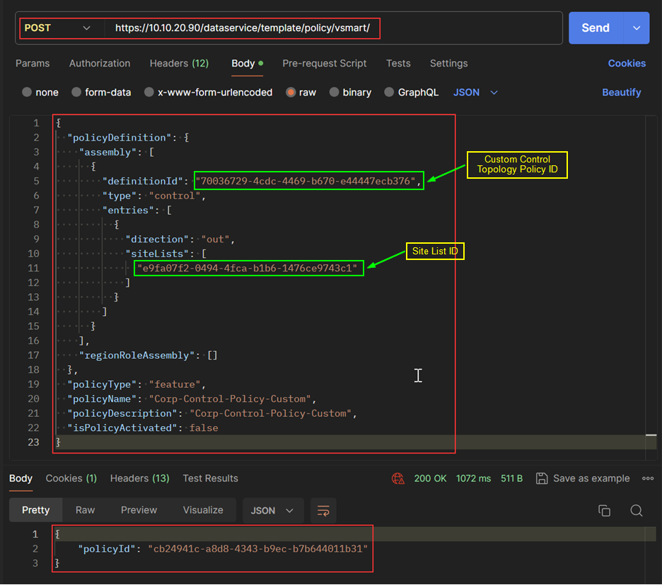
Create Custom Centralized Policy
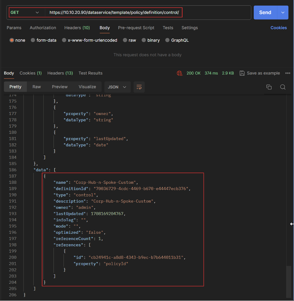
Get Custom Centralized Policy
- Activate Policy
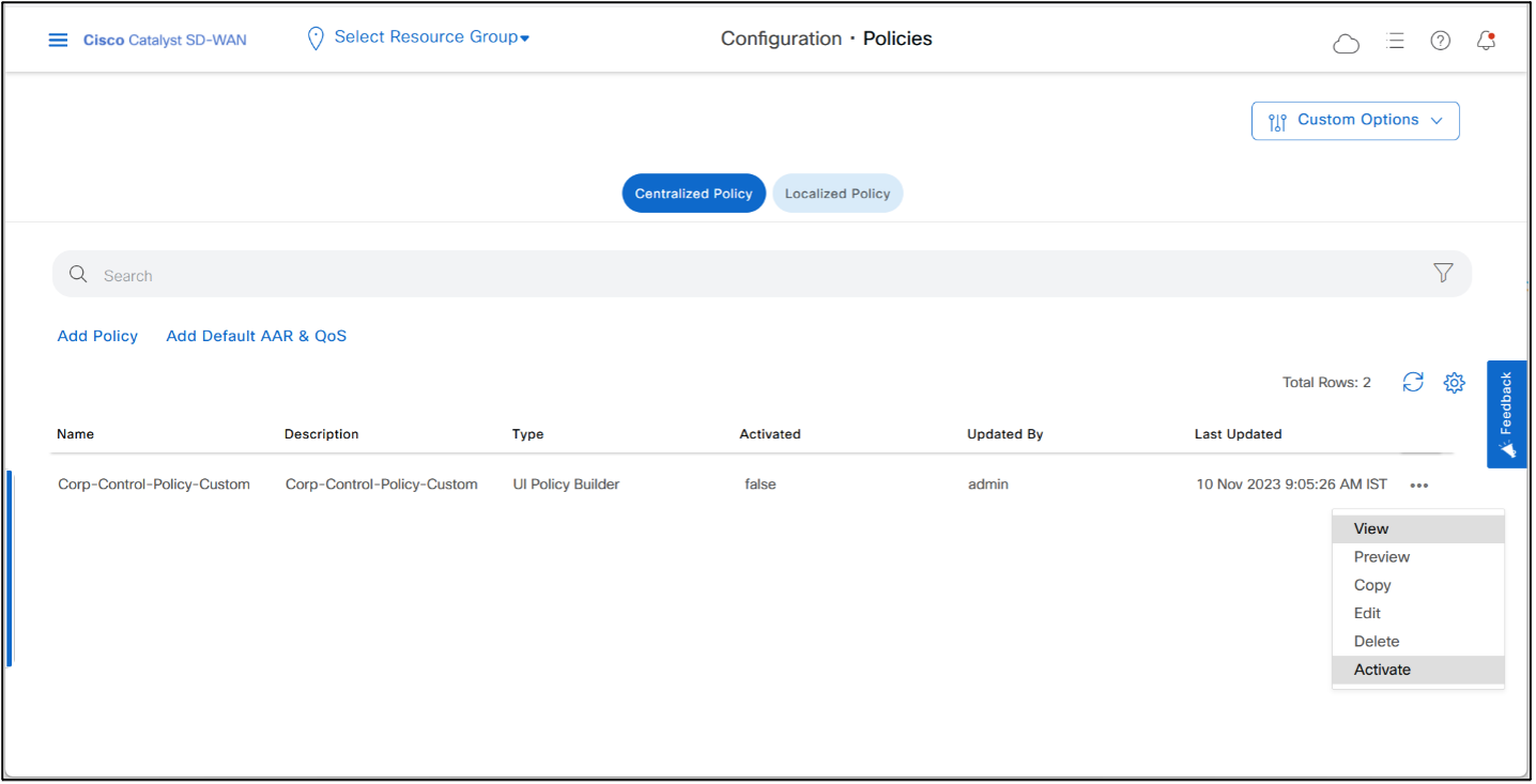
- Click Activate
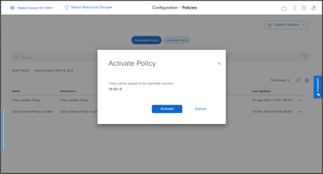
- Click Activate once again.
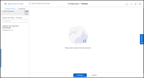
- Policy is successfully pushed to the Controller.
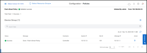
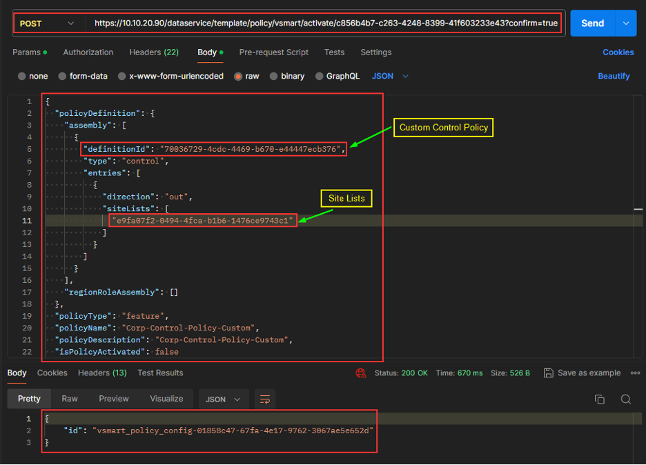
REST API
Activate Policy
Let’s check the routing tables on Site1 and Site2 cEdges.
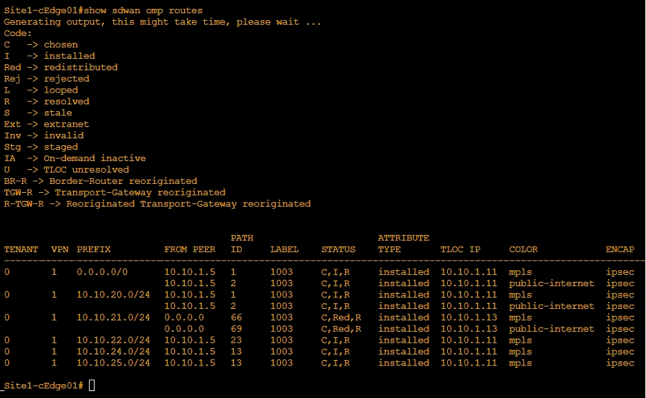
- OMP table on Site1-cEdge01 shows that in VPN 1 the Next-Hop of Site2-cEdge01 route is now DC TLOC.
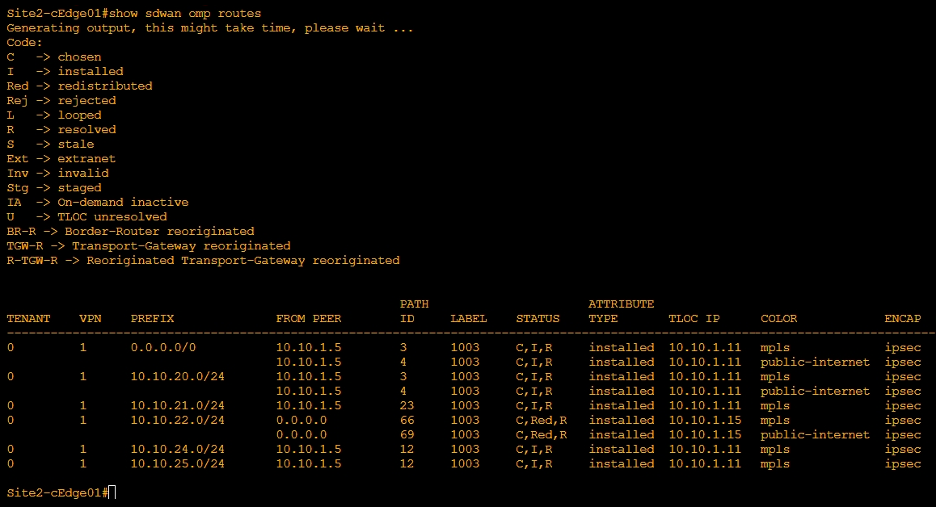
- Similarly, Site2-cEdge01 shows that in VPN 1 the Next-Hop of Site1-cEdge01 route is now DC TLOC.
Let’s test this using the traceroute as well.
- Go to Monitor > Devices > Site1-cEdge01 > Troubleshooting > Trace Route
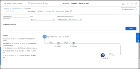
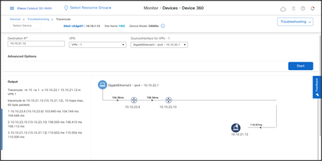
Traceroute confirms that traffic from Site1 takes one-hop through DC site to reach Site2.
Traffic from Site2 to a host in Site1 confirms the hub-and-spoke topology as well.
Deactivate the Policy when not required.
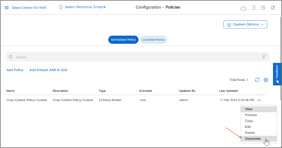
REST API
Deactivate Policy.
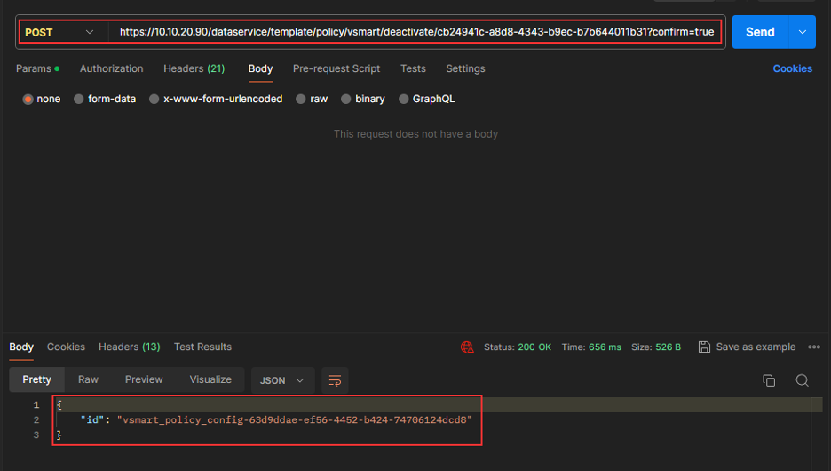
Cisco Catalyst SD-WAN Manager Support for SD-Routing
Description:
This feature allows basic management of Cisco IOS XE devices that operate in autonomous (non-SD-WAN) mode through Cisco Catalyst SD-WAN Manager. We refer to these devices as SD-Routing devices. Teams can use a single NMS (Cisco SD-WAN Manager) for both Cisco Catalyst SD-WAN and SD-Routing devices.
Onboarding SD-Routing Devices
You can onboard SD-Routing devices by using the following methods:
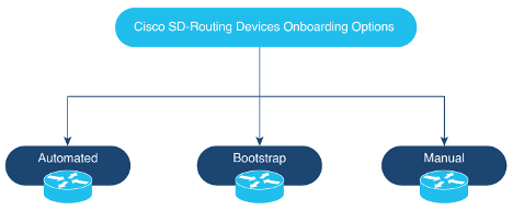
-Automated Onboarding: Uses Dynamic Host Configuration Protocol (DHCP) and Cisco Plug and Play (PNP) to automatically onboard the device to Cisco Catalyst SD-WAN Manager.
-Bootstrap Onboarding: Uses bootstrap file either on the bootflash or on a USB and configures the device with the minimum configuration to reach Cisco Catalyst SD-WAN Manager.
-Manual Onboarding: Configures device manually using IOS-XE commands to onboard the device to Cisco Catalyst SD-WAN Manager.
In this guide we’ll use Manual Onboarding procedure.
Manual Onboarding Configuration
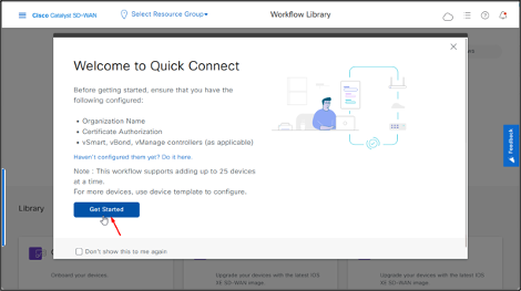
- From Cisco Catalyst SD-WAN Manager menu, go to Workflows > Quick Connect.
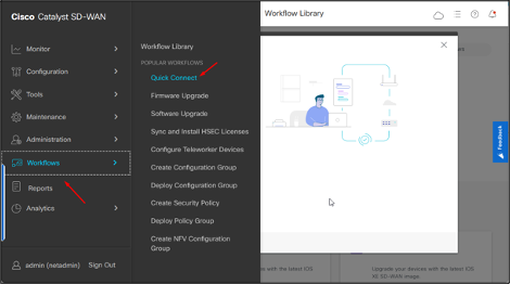
- Click Get Started.
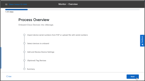
- Click Next.
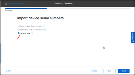
 If the provisioning file (.csv or .viptela) is not uploaded from PnP to Cisco Catalyst SD-WAN Manager, you can use either Login to your Smart Account (Sync Smart Account) option or Upload file with serial numbers (.csv or .viptela) upload option to add the device to Cisco Catalyst SD-WAN Manager. If the device is already added to Cisco Catalyst SD-WAN Manager, select Skip for now option.
Note:
- .csvfile is applicable only for hardware devices,.viptelafile is applicable for both hardware and software devices.
- In this Lab, devices serial file has been already uploaded to Cisco Catalyst SD-WAN Manager, therefore choose Skip for now option, and click Next.
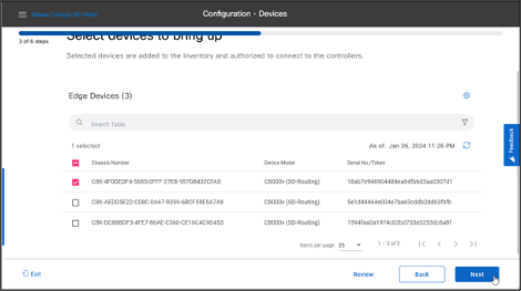
- Select the device that you want to onboard and click Next.
- In the Add and Review Configuration dialog box, enter the Site-ID, **System-IP, and Hostname.
- Click Export to download the file, fill the details and then Import it.
- Click Apply and then click Next.
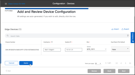
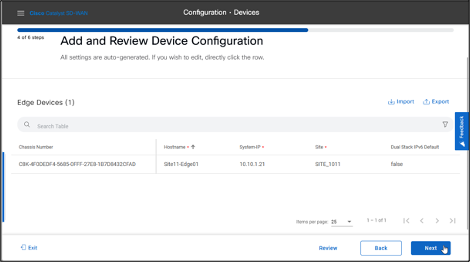
- Check the details, then click Next.
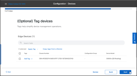
- Check the Summary, then click Onboard.

REST API Onboard SD-Routing Device
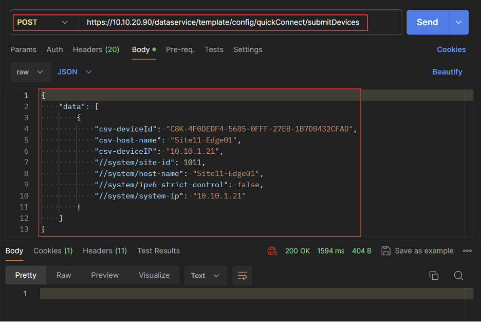
- Activate the device using Chassis and Token.
- Log in to CML and go to Site11-Edge01 console.
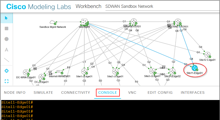
- Run the following command on the device console.
request platform soft sd-routing activate chassis
token
You can obtain the Chassis ID and Token number from Cisco Catalyst SD-WAN Manager. Go to Cisco Catalyst SD-WAN Manager > Configuration > Certificates
Note: Cisco SD-WAN software devices (Cisco C8000V) support this method.
- Verify the control connection status on the Edge device using these commands:
show sd-routing connections summary

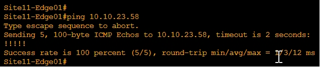
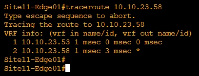
Verify connectivity to another SD-Routing device.
- Ping Site12 from Site11
-Traceroute Site12 from Site11
Route Leaking
This feature enables the capability to leak routes between VRFs.
Route Leaking between Global VRF and Service VPNs
This feature enables you to leak routes bidirectionally between Global VRF and Service VPNs. It allows bypassing hubs and provides migrated branches direct access to non-migrated branches.
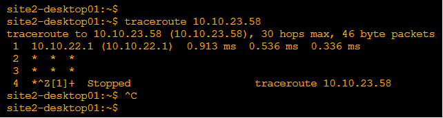
Configure Route Leaking in Site2, so that Site2 LAN has reachability to Site12 (non SD-WAN site) via Underlay.
Pre-Check
- Traceroute from Site2 VPN1 to Site12
Configuration:
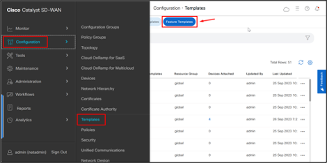
From Cisco Catalyst SD-WAN Manager menu, choose Configuration > Templates.
Click Feature Templates.
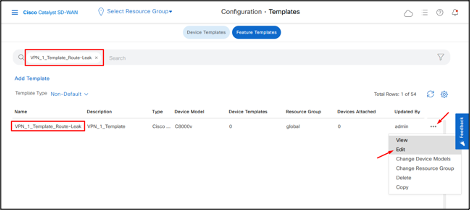
- Search for “VPN_1_Template_Route-Leak” template, click on the 3 dots and then click Edit.
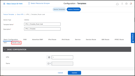
- Go to Route Leak section.
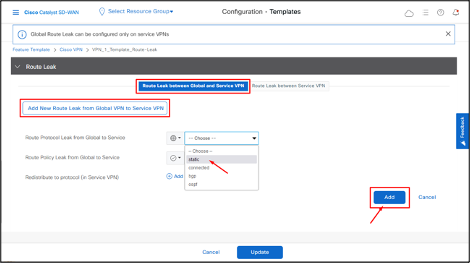
- To leak routes from global VRF, click Add New Route Leak from Global VPN to Service VPN.
In the Route Protocol Leak from Global to Service drop-down list, choose protocol as Static.
Click Add.
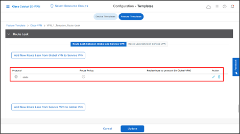
- To leak routes from the service VPNs to global VRF, click Add New Route Leak from Service VPN to Global VPN.
- In the Route Protocol Leak from Service to Global drop-down list, select Global and then choose protocol as connected.
- Click Add.
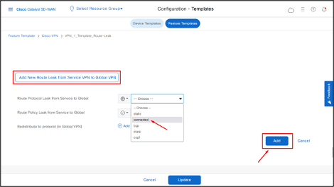
- Click Update.
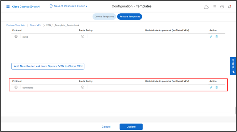
- Click Next.
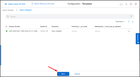
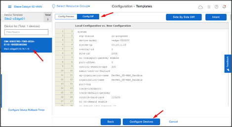
Select the device and then click Config Diff to check the changes that the system will push to the device.
Click Configure Devices.
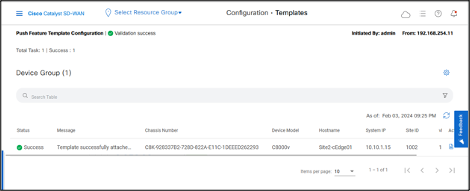
- Once the system pushes the configuration to the device, the status displays as Success.
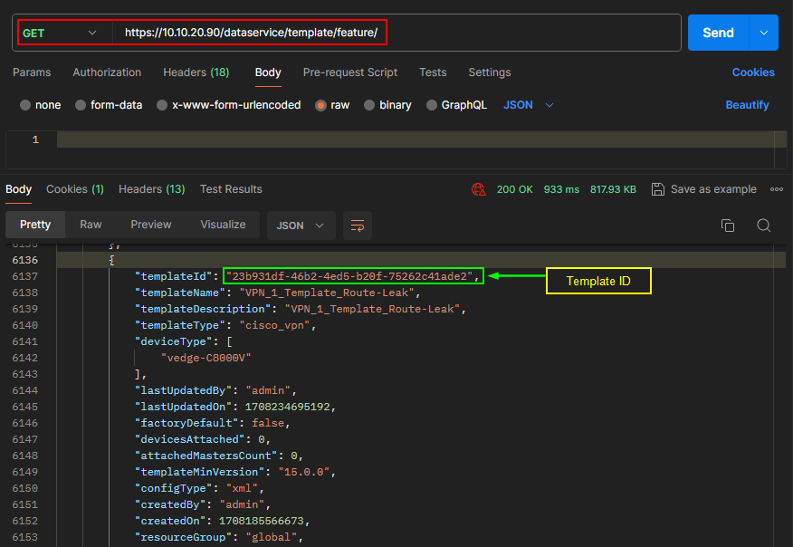
REST API
Get all Feature Templates List.
Configure Route Leaking in VPN_1_Template_Route-Leak Template.
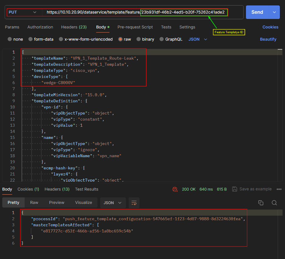
Push Template changes to the device.
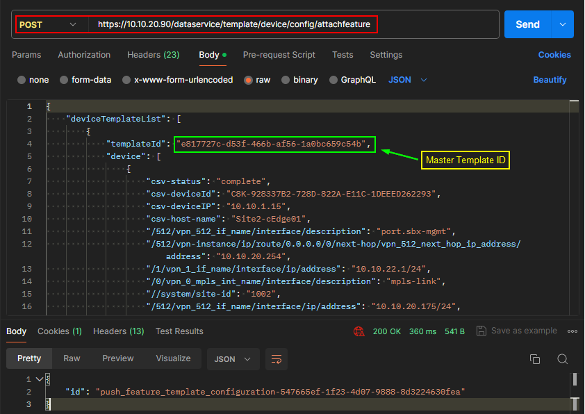
Verification
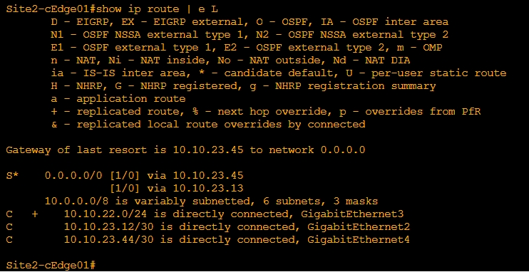
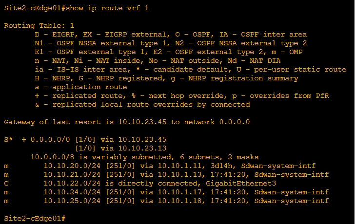
Verify Route Leaking using following commands:
show ip route
show ip route vrf
In the output, a + sign next to a route represents a leaked route. Example: C+ denotes that the system leaks a connected route into Global VRF.
In the output, a + sign next to a route represents a leaked route. Example: S+ denotes that the system leaks a static route into Service VPN.
Testing
Ping Site12 (non sd-wan) from Site2 VRF1

Traceroute Site12 (non sd-wan) from Site2 VRF1

Route Leaking between Inter-Service VPN
With this feature, you can leak routes between the Service VPNs at the same Edge device.
Configuration:
Configure Route Leaking in Site2, so that Site2 redistributes VRF2 routes to VRF1.
From the Cisco Catalyst SD-WAN Manager menu, choose Configuration > Templates.
Click Feature Templates.
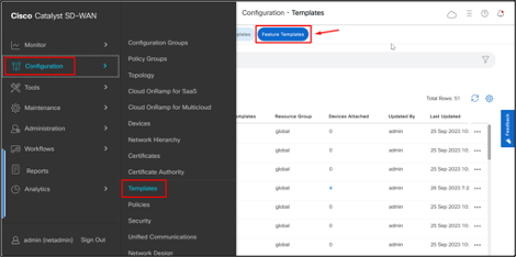
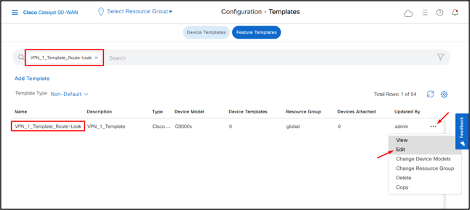
- Search for “VPN_1_Template_Route-Leak” template, click on the 3 dots and then click Edit.
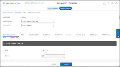
- Click Route Leak field.
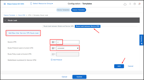
- Click Route Leak between Service VPN.
- Click Add New Inter Service VPN Route Leak.
- In the Source VPN drop-down list, choose the service VPN from where you want to leak the routes.
- In the Route Protocol Leak to Current VPN drop-down list, select a route protocol to enable route leaking to the current VPN.
- Click Add.
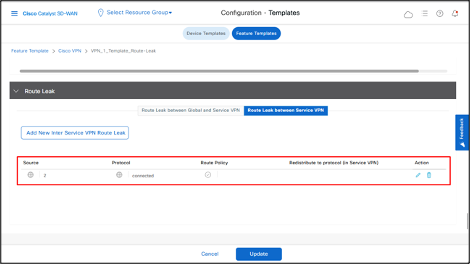
- Click Update.
- Click Next.
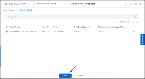
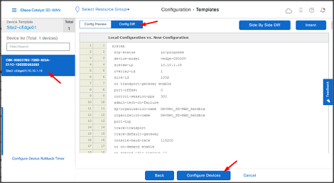
Select the device and then click Config Diff to check the changes that the system will push to the device.
Then click Configure Devices.
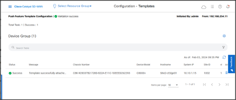
- Once the system pushes the configuration to the device, the status displays as Success.
REST API
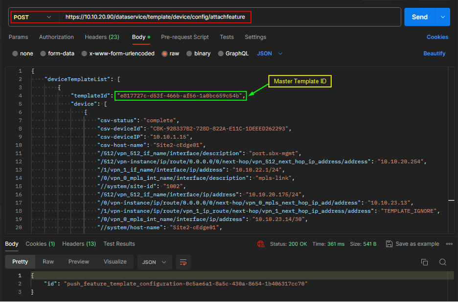
Configure Route Leak in VPN_1_Template_Route-Leak Template.
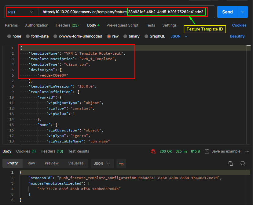
Push Template changes to the device.
Verification
Verify Route Leaking using following commands:
show ip route vrf
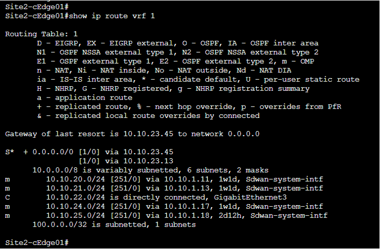
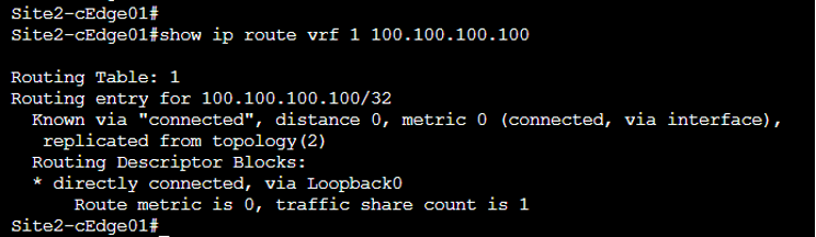
The following output shows that the system redistributes VRF2 route (100.0.0.0/32) to VRF1.
UX 2.0 Config Group Deployment
Note: Keep the running configuration of the target device handy/copied to a notepad before deploying the Configuration Group. Ensure that you detach the device from device templates. (The target device in this example will be Site1-cEdge01.)
Login to Cisco Catalyst SD-WAN Manager at select the main dashboard, Navigate to Configuration > Configuration Groups. Select Add Configuration Group.
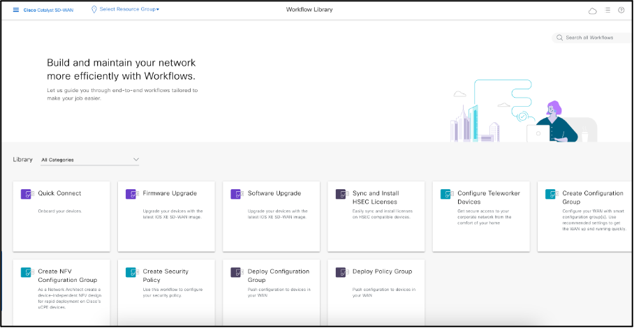
This opens Workflow Library, from this menu choose Create Configuration Group
A “Welcome to Configuration Group Creation “ Banner appears, select Let’s Do it.
Name and Describe the Configuration Group. For the sake of this Lab Guide let’s name it as Site1_EC.
Following menu appears as shown below.
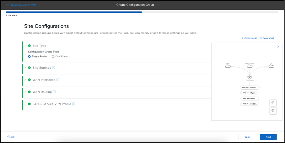
Select the Site Type as Single Router. Hop on to WAN Interfaces, as You select three transport types namely MPLS, Internet and LTE appear, add the details of Interface name by clicking Show Advanced check box, delete the LTE transport. Select Static IP and provide the IP details of these transports.
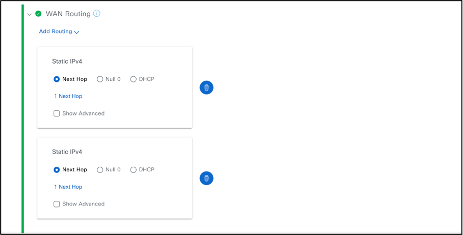
Add WAN Routing, Select Static IPv4 from the drop-down menu and since we have two TLOC’s we choose two Static IPv4 entries as shown below.
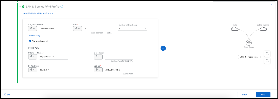
- Select LAN & Service VPN Profile, add the Service VPN number followed by the number of interfaces under this VPN. Remove/Delete the additional Service VPNs that is not required or present in your deployment.
Enable Remote Access if necessary; otherwise, the system disables it by default. Click Next.
Review the Summary of the Configuration Group, edit anything if it seems incorrect.
Once confirmed, click Create Configuration Group. The user receives success messages for all individual items. Once you create the Configuration Group, select Associate Devices.
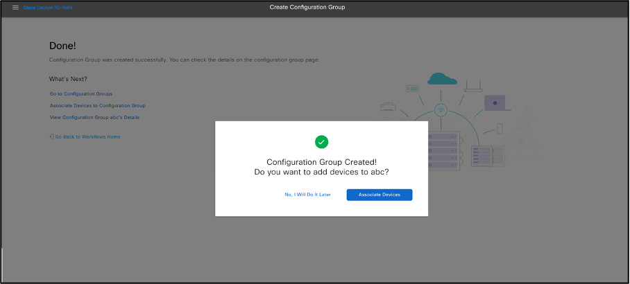
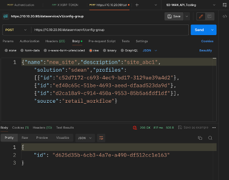
The configuration group you created above is equivalent to the API call below:
POST https://10.10.20.90/dataservice/v1/config-group
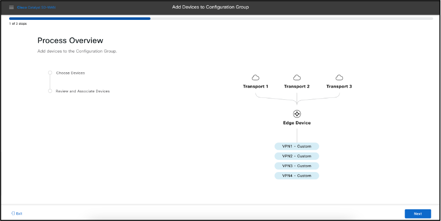
Add devices to the Configuration Group, select Next to below step.
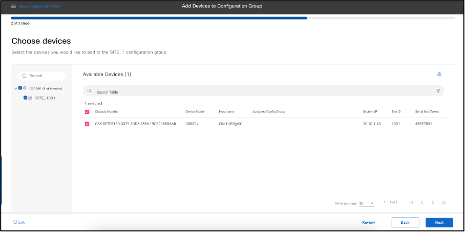
- Select the target device from the list. Select Site_1001 under Global. You can see the target device Chassi Number along with hostname, System IP, Site ID, and serial number, then select the device as shown below.
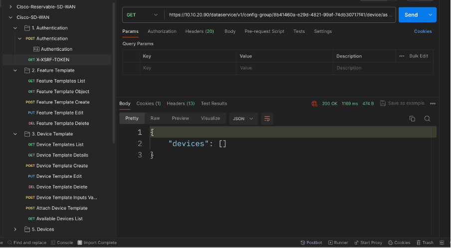
If you see no device in this list, it means you detached none by using templates. In that case, the GET API looks as shown below.
Review the Summary for the device that you want to add. You can deploy the device now or later.
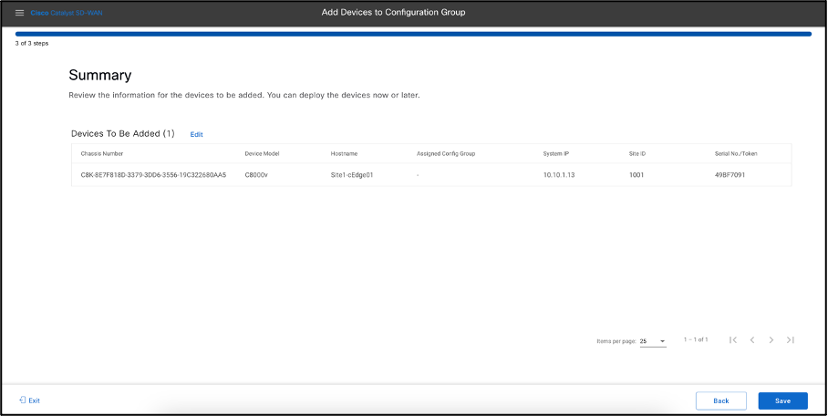
Click on Save. Following message appears.
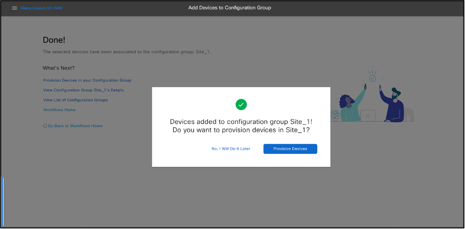
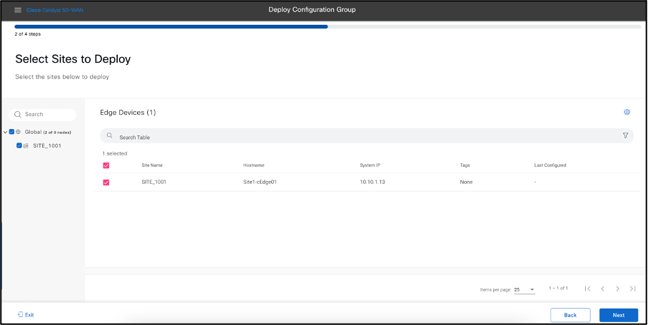
- Select Provision Devices and select Next. Select Sites to Deploy. Click Next.
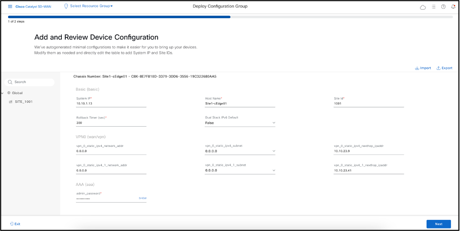
- Add and Review Device Configuration. Cisco Catalyst SD-WAN Manager autogenerated minimal configurations to make it easier.
- Review the Summary of the device followed by Deploy
- Select Deploy.
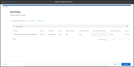
- Deployment request for the device gets submitted, select View Deployment Status
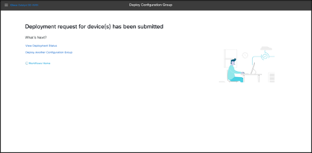
- You receive a success status message, as shown below.
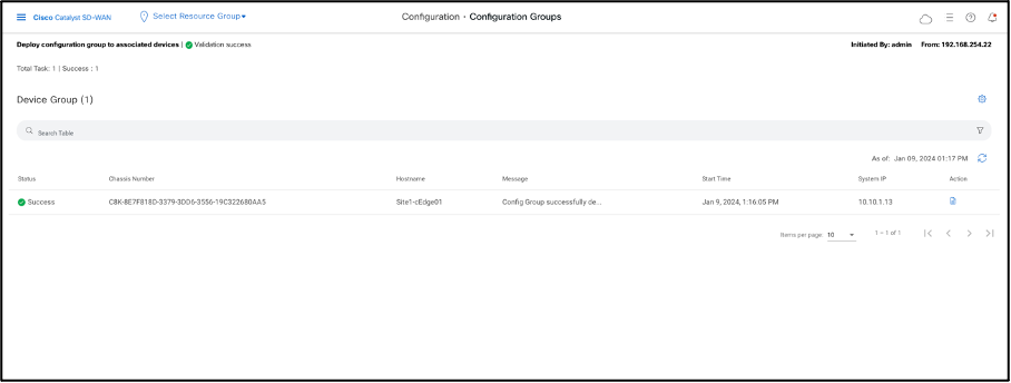
- The above action against attaching the device shows up as below API
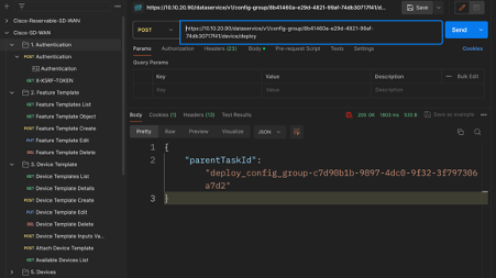
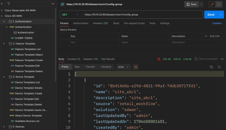
- Essentially view the existing Config Groups using the below API
GET https://10.10.20.90/dataservice/v1/config-group
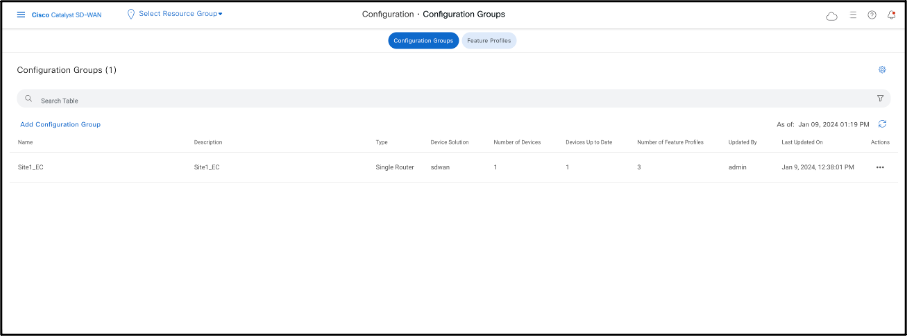
Click on Configuration > Configuration Group to view the newly created CG for Site1 cEdge, as shown below.
Creating Tags using UX2.0
Navigate to Configuration > Devices
Let’s Go ahead and assign Tags to devices at Site3, select Site3-cEdge01
POST https://10.10.20.90/dataservice/v1/tags/associate
On similar lines, I have now created a tag named Europe1, as shown below.
Let’s verify whether the same appears on Cisco Catalyst SD-WAN Manager.
Global Site Topology using UX2.0
As seen we have onboarded Site1-cEdge01 to Config Groups, we can now view the Global Topology view for this device.
SITE_1001 Site1-cEdge01
Select the last icon in the Overview tab.
Select the Network Hierarchy in the left panel and select Site_1001.
This dashlet shows the device health for Site1-cEdge01. Select the Global Topology icon, as shown below.
Admin can see the Global Network Topology for this device, the WAN TLOCs and Service VPNs onboarded as seen below.
The above is basically a GET API at the backend, below is the API and its payload.
GET: https://10.10.20.90/dataservice/topology/monitor/site/1001
RBAC Using Resource Group
This use case demonstrates how a user within a resource group can have restricted access to default permissions available in Cisco Catalyst SD-WAN Manager.
Go to the main dashboard, Navigate to Administration > Manage Users.
Select User Groups and create the custom role, in this case site1_service.
Select the features of interest for which the created user needs read/write access. For testing purposes, I enabled the following features for this group named site1_service. Other than monitoring and license management, limit the user to the service side of the config group.
Below is the API that fetches user groups on Cisco Catalyst SD-WAN Manager.
GET https://10.10.20.90/dataservice/admin/usergroup
Focus on the body of this GET call
We truncated the output; you can see the newly created user group site1_service with the defined read/write feature access.
Define a Resource Group. In this reference, we name the site America, specific to Site2 only.
Admin must manually change the resource group for the device templates and feature templates to America.
Next, define the user. Navigate to Users at the top and create a user. In this example, we add user Wen. For 17.12, we can use only the predefined default roles and cannot use a custom role.
API Call to create a user:
POST: https://10.10.20.90/dataservice/admin/user
Admin can now log out and log in in via username Wen to view the level of access.
The new user Wen can see only the templates that admins attached to America and Global. Also, this user can edit the template that admins assigned to Site2-cEdge01, while having only view access to global templates.
License Management
Navigate to Administration > License Management
For this reference example, the setup uses offline mode. Navigate to Administration Settings and select License Reporting as Offline; below is the PUT API call for this function.
In either of the modes the admin must sync their SA/VA. Next step would be to go ahead and sync the license file, below is the API call for the same task.
POST: https://10.10.20.90/dataservice/smartLicensing/syncLicenses
Admin must download their License Summary file from their SA/VA, this is a tar.gz file. While making this POST call, the system requests the above-mentioned summary file, and you must upload it to form-data under Body.
Select Devices, choose the desired one, and select Assign License/Subscription.
While assigning the license to Site3-cEdge01, the system pushes the POST API call below. The following body shows the chassis ID for device Site3-cEdge01, a prepaid license type, template name temp1, SA/VA details, the MSLA flag as false for prepaid licenses, and the assigned license reg ID with the name.