3-Stage Clos Network with Static VXLAN
Try out this use case on Interactive Python Notebooks
Modern cloud-scale data center networks require increased server-to-server communication over a network that stays resilient despite the rapid increase in the number of devices.
A 3-stage Clos network interconnects data center network switches where each spine switch connects to all leaf switches. And each leaf switch connects to a server in the data center. Any server in the data center is just three hops away from another server. The first hop is from the server to the directly connected leaf switch, the second hop is across the spine switches to the destination leaf switch, and the third hop is between the destination leaf switch to the destination server. This network architecture is highly scalable. Also, irrespective of the number of devices in the data center, the number of hops between the servers or the end-hosts is always 3, ensuring consistent latency in the data center network.
The 3-stage Clos network is a robust IP-BGP underlay network for the data center. Over this network, you can configure overlay features such as Virtual Extensible Local Area Network (VXLAN).
VXLAN is a tunneling protocol that stretches Layer 2 networks over an underlying Layer 3 IP network by encapsulating Layer 2 Ethernet frames within Layer 4 User Datagram Protocol (UDP). It then transports the encapsulated frames over a Layer 3 network.
You can create up to 16 million VXLANs instead of the traditional VLAN, which allows only 4096 VLANs in a network. Thus, VXLAN enables the building of highly scalable networks with physically distant Layer 2 network segments.
There are two types of VXLANS:
Ethernet virtual private network (EVPN) VXLANs - EVPN provides the control plane functionality for these VXLANs.
Static VXLANs - There is no control plane for static VXLANs. So you should manually configure virtual tunnel end points and routes.
This notebook demonstrates how to Bring Up 3-Stage Clos Network as an Underlay Network using Cisco 8000 series routers that run SONiC. You can then Configure Static VXLANs over the 3-Stage Clos Network.
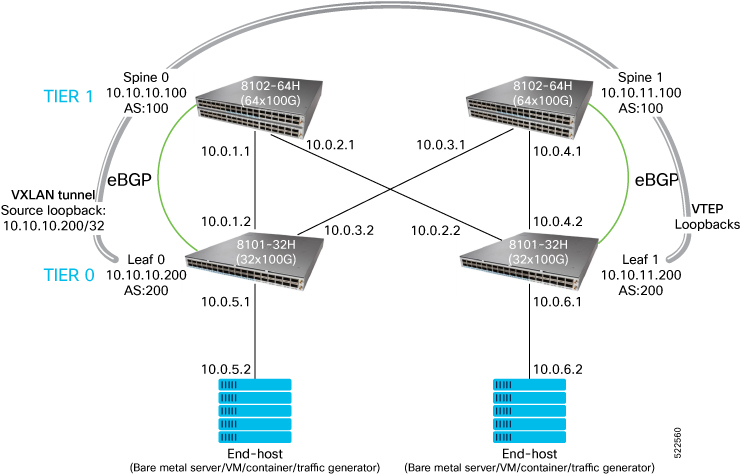
The following topology diagram depicts a simple 3-stage Clos network with two leaf routers in tier-0 and two spine routers in tier-1.

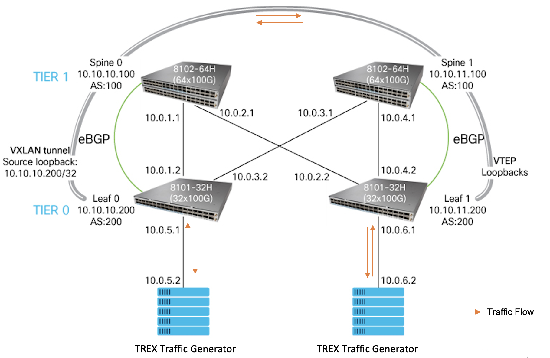
This topology shows the static VXLAN overlay on the 3-stage Clos network:
Connect the devices as per the first topology diagram and log into their SSH or telnet consoles.
Bring Up 3-Stage Clos Network as an Underlay Network
The following steps show you how to configure a 3-stage Clos network.
Configure Host-Names
Configure host names for the spine and leaf routers for easy identification.
cisco@sonic:~$ sudo config hostname LEAF0
Running command: service hostname-config restart
Reloading Monit configuration ...
Reinitializing monit daemon
Please note loaded setting will be lost after system reboot. To preserve setting, run `config save`.
cisco@LEAF0:~$ sudo config save -y
Running command: /usr/local/bin/sonic-cfggen -d --print-data > /etc/sonic/config_db.json
cisco@sonic:~$ sudo config hostname LEAF1
Running command: service hostname-config restart
Reloading Monit configuration ...
Reinitializing monit daemon
Please note loaded setting will be lost after system reboot. To preserve setting, run `config save`.
cisco@LEAF1:~$ sudo config save -y
Running command: /usr/local/bin/sonic-cfggen -d --print-data > /etc/sonic/config_db.json
cisco@sonic:~$ sudo config hostname SPINE0
Running command: service hostname-config restart
Reloading Monit configuration ...
Reinitializing monit daemon
Please note loaded setting will be lost after system reboot. To preserve setting, run `config save`.
cisco@SPINE0:~$ sudo config save -y
Running command: /usr/local/bin/sonic-cfggen -d --print-data > /etc/sonic/config_db.json
cisco@sonic:~$ sudo config hostname SPINE1
Running command: service hostname-config restart
Reloading Monit configuration ...
Reinitializing monit daemon
Please note loaded setting will be lost after system reboot. To preserve setting, run `config save`.
cisco@SPINE1:~$ sudo config save -y
Running command: /usr/local/bin/sonic-cfggen -d --print-data > /etc/sonic/config_db.json
Assign IP addresses
The following snippet shows you how to assign IP addresses on the various interfaces as per the topology diagram at the beginning of this use case.
cisco@LEAF0:~$ sudo config interface ip add Ethernet0 10.0.1.2/24
cisco@LEAF0:~$ sudo config interface ip add Ethernet1 10.0.3.2/24
cisco@LEAF0:~$ sudo config interface ip add Ethernet2 10.0.5.1/24
cisco@LEAF0:~$ sudo config interface ip add Loopback0 10.10.10.200/32
cisco@LEAF0:~$ sudo config save -y
Running command: /usr/local/bin/sonic-cfggen -d --print-data > /etc/sonic/config_db.json
cisco@LEAF1:~$ sudo config interface ip add Ethernet0 10.0.2.2/24
cisco@LEAF1:~$ sudo config interface ip add Ethernet1 10.0.4.2/24
cisco@LEAF1:~$ sudo config interface ip add Ethernet2 10.0.6.1/24
cisco@LEAF1:~$ sudo config interface ip add Loopback0 10.10.11.200/32
cisco@LEAF1:~$ sudo config save -y
Running command: /usr/local/bin/sonic-cfggen -d --print-data > /etc/sonic/config_db.json
cisco@SPINE0:~$ sudo config interface ip add Ethernet0 10.0.1.1/24
cisco@SPINE0:~$ sudo config interface ip add Ethernet1 10.0.2.1/24
cisco@SPINE0:~$ sudo config interface ip add Loopback0 10.10.10.100/32
cisco@SPINE0:~$ sudo config save -y
Running command: /usr/local/bin/sonic-cfggen -d --print-data > /etc/sonic/config_db.json
cisco@SPINE1:~$ sudo config interface ip add Ethernet0 10.0.3.1/24
cisco@SPINE1:~$ sudo config interface ip add Ethernet1 10.0.4.1/24
cisco@SPINE1:~$ sudo config interface ip add Loopback0 10.10.11.100/32
cisco@SPINE1:~$ sudo config save -y
Running command: /usr/local/bin/sonic-cfggen -d --print-data > /etc/sonic/config_db.json
[root@localhost ~]# ifconfig eth1 10.0.5.2 netmask 255.255.255.0 up
[root@localhost ~]# ifconfig eth2 10.0.6.2 netmask 255.255.255.0 up
Verify the configured IP addresses using the show ip interfaces command on the routers and ifconfig -a command on the TREX server.
cisco@LEAF0:~$ show ip interfaces
Interface    Master    IPv4 address/mask    Admin/Oper    BGP Neighbor    Neighbor IP
-----------  --------  -------------------  ------------  --------------  -------------
Ethernet0              10.0.1.2/24          up/up         N/A             N/A
Ethernet1              10.0.3.2/24          up/up         N/A             N/A
Ethernet2              10.0.5.1/24          up/up         N/A             N/A
Loopback0              10.10.10.200/32      up/up         N/A             N/A
docker0                240.127.1.1/24       up/down       N/A             N/A
eth0                   192.168.122.155/24   up/up         N/A             N/A
eth4                   192.168.123.52/24    up/up         N/A             N/A
lo                     127.0.0.1/16         up/up         N/A             N/A
cisco@LEAF1:~$ show ip interfaces
Interface    Master    IPv4 address/mask    Admin/Oper    BGP Neighbor    Neighbor IP
-----------  --------  -------------------  ------------  --------------  -------------
Ethernet0              10.0.3.1/24          up/up         N/A             N/A
Ethernet1              10.0.4.1/24          up/up         N/A             N/A
Loopback0              10.10.11.100/32      up/up         N/A             N/A
docker0                240.127.1.1/24       up/down       N/A             N/A
eth0                   192.168.122.253/24   up/up         N/A             N/A
eth4                   192.168.123.147/24   up/up         N/A             N/A
lo                     127.0.0.1/16         up/up         N/A             N/A
cisco@SPINE0:~$ show ip interfaces
Interface    Master    IPv4 address/mask    Admin/Oper    BGP Neighbor    Neighbor IP
-----------  --------  -------------------  ------------  --------------  -------------
Ethernet0              10.0.1.2/24          up/up         N/A             N/A
Ethernet1              10.0.3.2/24          up/up         N/A             N/A
Ethernet2              10.0.5.1/24          up/up         N/A             N/A
Loopback0              10.10.10.200/32      up/up         N/A             N/A
docker0                240.127.1.1/24       up/down       N/A             N/A
eth0                   192.168.122.170/24   up/up         N/A             N/A
eth4                   192.168.123.140/24   up/up         N/A             N/A
lo                     127.0.0.1/16         up/up         N/A             N/A
cisco@SPINE1:~$ show ip interfaces
Interface    Master    IPv4 address/mask    Admin/Oper    BGP Neighbor    Neighbor IP
-----------  --------  -------------------  ------------  --------------  -------------
Ethernet0              10.0.2.2/24          up/up         N/A             N/A
Ethernet1              10.0.4.2/24          up/up         N/A             N/A
Ethernet2              10.0.6.1/24          up/up         N/A             N/A
Loopback0              10.10.11.200/32      up/up         N/A             N/A
docker0                240.127.1.1/24       up/down       N/A             N/A
eth0                   192.168.122.102/24   up/up         N/A             N/A
eth4                   192.168.123.243/24   up/up         N/A             N/A
lo                     127.0.0.1/16         up/up         N/A             N/A
[root@localhost ~]# ifconfig -a eth1
eth1: flags=4163<UP,BROADCAST,RUNNING,MULTICAST>  mtu 1500
        inet 10.0.5.2  netmask 255.255.255.0  broadcast 10.0.5.255
        ether 02:80:01:1c:68:81  txqueuelen 1000  (Ethernet)
        RX packets 0  bytes 0 (0.0 B)
        RX errors 0  dropped 0  overruns 0  frame 0
        TX packets 177  bytes 29238 (28.5 KiB)
        TX errors 0  dropped 0 overruns 0  carrier 0  collisions 0

[root@localhost ~]# ifconfig -a eth2
eth2: flags=4163<UP,BROADCAST,RUNNING,MULTICAST>  mtu 1500
        inet 10.0.6.2  netmask 255.255.255.0  broadcast 10.0.6.255
        ether 02:d9:3e:32:b8:c1  txqueuelen 1000  (Ethernet)
        RX packets 0  bytes 0 (0.0 B)
        RX errors 0  dropped 0  overruns 0  frame 0
        TX packets 178  bytes 29580 (28.8 KiB)
        TX errors 0  dropped 0 overruns 0  carrier 0  collisions 0
Configure eBGP
For the eBGP (exterior Border Gateway Protocol) configuration, the spine routers are in Autonomous System (AS) 100 and the leaf routers in AS 200.
cisco@LEAF0:~$ vtysh

Hello, this is FRRouting (version 7.5.1-sonic).
Copyright 1996-2005 Kunihiro Ishiguro, et al.

LEAF0# configure terminal
LEAF0(config)# router-id 10.10.10.200
LEAF0(config)# router bgp 200
LEAF0(config-router)# no bgp ebgp-requires-policy
LEAF0(config-router)# neighbor 10.0.1.1 remote-as 100
LEAF0(config-router)# neighbor 10.0.3.1 remote-as 100
LEAF0(config-router)# address-family ipv4 unicast
LEAF0(config-router-af)# neighbor 10.0.1.1 allowas-in
LEAF0(config-router-af)# neighbor 10.0.3.1 allowas-in
LEAF0(config-router-af)# network 10.0.1.0/24
LEAF0(config-router-af)# network 10.0.3.0/24
LEAF0(config-router-af)# network 10.0.5.0/24
LEAF0(config-router-af)# network 10.10.10.200/32
LEAF0(config-router-af)# redistribute connected
LEAF0(config-router-af)# ^Z
cisco@LEAF1:~$ vtysh

Hello, this is FRRouting (version 7.5.1-sonic).
Copyright 1996-2005 Kunihiro Ishiguro, et al.

LEAF1# configure terminal
LEAF1(config)# router-id 10.10.11.200
LEAF1(config)# router bgp 200
LEAF1(config-router)# no bgp ebgp-requires-policy
LEAF1(config-router)# neighbor 10.0.2.1 remote-as 100
LEAF1(config-router)# neighbor 10.0.4.1 remote-as 100
LEAF1(config-router)# address-family ipv4 unicast
LEAF1(config-router-af)# neighbor 10.0.2.1 allowas-in
LEAF1(config-router-af)# neighbor 10.0.4.1 allowas-in
LEAF1(config-router-af)# network 10.0.2.0/24
LEAF1(config-router-af)# network 10.0.4.0/24
LEAF1(config-router-af)# network 10.0.6.0/24
LEAF1(config-router-af)# network 10.10.11.200/32
LEAF1(config-router-af)# redistribute connected
LEAF1(config-router-af)# ^Z
cisco@SPINE0:~$ vtysh

Hello, this is FRRouting (version 7.5.1-sonic).
Copyright 1996-2005 Kunihiro Ishiguro, et al.

SPINE0# configure terminal
SPINE0(config)# router-id 10.10.10.100
SPINE0(config)# router bgp 100
SPINE0(config-router)# no bgp ebgp-requires-policy
SPINE0(config-router)# neighbor 10.0.2.2 remote-as 200
SPINE0(config-router)# neighbor 10.0.1.2 remote-as 200
SPINE0(config-router)# address-family ipv4 unicast
SPINE0(config-router-af)# neighbor 10.0.2.2 allowas-in
SPINE0(config-router-af)# neighbor 10.0.1.2 allowas-in
SPINE0(config-router-af)# network 10.0.1.0/24
SPINE0(config-router-af)# network 10.0.2.0/24
SPINE0(config-router-af)# network 10.10.10.100/32
SPINE0(config-router-af)# redistribute connected
SPINE0(config-router-af)# ^Z
cisco@SPINE1:~$ vtysh

Hello, this is FRRouting (version 7.5.1-sonic).
Copyright 1996-2005 Kunihiro Ishiguro, et al.

SPINE1# configure terminal
SPINE1(config)# router-id 10.10.11.100
SPINE1(config)# router bgp 100
SPINE1(config-router)# no bgp ebgp-requires-policy
SPINE1(config-router)# neighbor 10.0.3.2 remote-as 200
SPINE1(config-router)# neighbor 10.0.4.2 remote-as 200
SPINE1(config-router)# address-family ipv4 unicast
SPINE1(config-router-af)# neighbor 10.0.3.2 allowas-in
SPINE1(config-router-af)# neighbor 10.0.4.2 allowas-in
SPINE1(config-router-af)# network 10.0.3.0/24
SPINE1(config-router-af)# network 10.0.4.0/24
SPINE1(config-router-af)# network 10.10.11.100/32
SPINE1(config-router-af)# redistribute connected
SPINE1(config-router-af)# ^Z
Execute the command show bgp summary on all tier-0 and tier-1 routers. Since eBGP interconnects different AS, verify that the local AS number and the AS number of the neighbor are different.
LEAF0# show bgp summary

IPv4 Unicast Summary:
BGP router identifier 10.10.10.200, local AS number 200 vrf-id 0
BGP table version 12
RIB entries 25, using 4800 bytes of memory
Peers 2, using 43 KiB of memory

Neighbor        V         AS   MsgRcvd   MsgSent   TblVer  InQ OutQ  Up/Down State/PfxRcd   PfxSnt
10.0.1.1        4        100        14        14        0    0    0 00:00:22           12       12
10.0.3.1        4        100        14        14        0    0    0 00:00:21           12       12

Total number of neighbors 2
LEAF1# show bgp summary
IPv4 Unicast Summary:
BGP router identifier 10.10.11.200, local AS number 200 vrf-id 0
BGP table version 16
RIB entries 25, using 4800 bytes of memory
Peers 2, using 43 KiB of memory

Neighbor        V         AS   MsgRcvd   MsgSent   TblVer  InQ OutQ  Up/Down State/PfxRcd   PfxSnt
10.0.2.1        4        100        14        17        0    0    0 00:00:05           12       12
10.0.4.1        4        100        14        17        0    0    0 00:00:05           12       12

Total number of neighbors 2
SPINE0# show bgp summary
Pv4 Unicast Summary:
BGP router identifier 10.10.10.100, local AS number 100 vrf-id 0
BGP table version 14
RIB entries 25, using 4800 bytes of memory
Peers 2, using 43 KiB of memory

Neighbor        V         AS   MsgRcvd   MsgSent   TblVer  InQ OutQ  Up/Down State/PfxRcd   PfxSnt
10.0.1.2        4        200        14        14        0    0    0 00:00:05           12       12
10.0.2.2        4        200        17        14        0    0    0 00:00:04           12       12

Total number of neighbors 2
SPINE1# show bgp summary
IPv4 Unicast Summary:
BGP router identifier 10.10.11.100, local AS number 100 vrf-id 0
BGP table version 14
RIB entries 25, using 4800 bytes of memory
Peers 2, using 43 KiB of memory

Neighbor        V         AS   MsgRcvd   MsgSent   TblVer  InQ OutQ  Up/Down State/PfxRcd   PfxSnt
10.0.3.2        4        200        14        14        0    0    0 00:00:05           12       12
10.0.4.2        4        200        17        14        0    0    0 00:00:04           12       12

Total number of neighbors 2
This section checks the routes learnt through BGP by executing the command show ip route on all routers in tier-0 and tier-1. The lines starting with the letter B are the routes learnt through BGP.
LEAF0# show ip route
Codes: K - kernel route, C - connected, S - static, R - RIP,
       O - OSPF, I - IS-IS, B - BGP, E - EIGRP, N - NHRP,
       T - Table, v - VNC, V - VNC-Direct, A - Babel, D - SHARP,
       F - PBR, f - OpenFabric,
       > - selected route, * - FIB route, q - queued, r - rejected, b - backup

K>* 0.0.0.0/0 [0/202] via 192.168.122.1, eth0, 00:33:54
C>* 10.0.1.0/24 is directly connected, Ethernet0, 00:23:57
B>* 10.0.2.0/24 [20/0] via 10.0.1.1, Ethernet0, weight 1, 00:09:15
C>* 10.0.3.0/24 is directly connected, Ethernet1, 00:23:40
B>* 10.0.4.0/24 [20/0] via 10.0.3.1, Ethernet1, weight 1, 00:09:14
C>* 10.0.5.0/24 is directly connected, Ethernet2, 00:23:29
B>* 10.0.6.0/24 [20/0] via 10.0.1.1, Ethernet0, weight 1, 00:09:13
  *                    via 10.0.3.1, Ethernet1, weight 1, 00:09:13
B>* 10.10.10.100/32 [20/0] via 10.0.1.1, Ethernet0, weight 1, 00:09:15
C>* 10.10.10.200/32 is directly connected, Loopback0, 00:23:18
B>* 10.10.11.100/32 [20/0] via 10.0.3.1, Ethernet1, weight 1, 00:09:14
B>* 10.10.11.200/32 [20/0] via 10.0.1.1, Ethernet0, weight 1, 00:09:13
  *                        via 10.0.3.1, Ethernet1, weight 1, 00:09:13
C>* 192.168.122.0/24 is directly connected, eth0, 00:33:54
C>* 192.168.123.0/24 is directly connected, eth4, 00:33:54
LEAF1# show ip route
Codes: K - kernel route, C - connected, S - static, R - RIP,
       O - OSPF, I - IS-IS, B - BGP, E - EIGRP, N - NHRP,
       T - Table, v - VNC, V - VNC-Direct, A - Babel, D - SHARP,
       F - PBR, f - OpenFabric,
       > - selected route, * - FIB route, q - queued, r - rejected, b - backup

B>* 10.0.1.0/24 [20/0] via 10.0.2.1, Ethernet0, weight 1, 00:00:10
C>* 10.0.2.0/24 is directly connected, Ethernet0, 00:00:32
B>* 10.0.3.0/24 [20/0] via 10.0.4.1, Ethernet1, weight 1, 00:00:09
C>* 10.0.4.0/24 is directly connected, Ethernet1, 00:00:31
B>* 10.0.5.0/24 [20/0] via 10.0.2.1, Ethernet0, weight 1, 00:00:09
  *                    via 10.0.4.1, Ethernet1, weight 1, 00:00:09
C>* 10.0.6.0/24 is directly connected, Ethernet2, 00:00:30
B>* 10.10.10.100/32 [20/0] via 10.0.2.1, Ethernet0, weight 1, 00:00:10
B>* 10.10.10.200/32 [20/0] via 10.0.2.1, Ethernet0, weight 1, 00:00:09
  *                        via 10.0.4.1, Ethernet1, weight 1, 00:00:09
B>* 10.10.11.100/32 [20/0] via 10.0.4.1, Ethernet1, weight 1, 00:00:09
C>* 10.10.11.200/32 is directly connected, Loopback0, 00:00:31
C>* 192.168.122.0/24 is directly connected, eth0, 00:09:29
C>* 192.168.123.0/24 is directly connected, eth4, 00:09:29
SPINE0# show ip route
Codes: K - kernel route, C - connected, S - static, R - RIP,
       O - OSPF, I - IS-IS, B - BGP, E - EIGRP, N - NHRP,
       T - Table, v - VNC, V - VNC-Direct, A - Babel, D - SHARP,
       F - PBR, f - OpenFabric,
       > - selected route, * - FIB route, q - queued, r - rejected, b - backup

C>* 10.0.1.0/24 is directly connected, Ethernet0, 00:00:42
C>* 10.0.2.0/24 is directly connected, Ethernet1, 00:00:41
B>* 10.0.3.0/24 [20/0] via 10.0.1.2, Ethernet0, weight 1, 00:00:09
B>* 10.0.4.0/24 [20/0] via 10.0.2.2, Ethernet1, weight 1, 00:00:08
B>* 10.0.5.0/24 [20/0] via 10.0.1.2, Ethernet0, weight 1, 00:00:09
B>* 10.0.6.0/24 [20/0] via 10.0.2.2, Ethernet1, weight 1, 00:00:08
C>* 10.10.10.100/32 is directly connected, Loopback0, 00:00:41
B>* 10.10.10.200/32 [20/0] via 10.0.1.2, Ethernet0, weight 1, 00:00:09
B>* 10.10.11.100/32 [20/0] via 10.0.1.2, Ethernet0, weight 1, 00:00:08
  *                        via 10.0.2.2, Ethernet1, weight 1, 00:00:08
B>* 10.10.11.200/32 [20/0] via 10.0.2.2, Ethernet1, weight 1, 00:00:08
C>* 192.168.122.0/24 is directly connected, eth0, 00:08:59
C>* 192.168.123.0/24 is directly connected, eth4, 00:08:59
SPINE1# show ip route
Codes: K - kernel route, C - connected, S - static, R - RIP,
       O - OSPF, I - IS-IS, B - BGP, E - EIGRP, N - NHRP,
       T - Table, v - VNC, V - VNC-Direct, A - Babel, D - SHARP,
       F - PBR, f - OpenFabric,
       > - selected route, * - FIB route, q - queued, r - rejected, b - backup

K>* 0.0.0.0/0 [0/202] via 192.168.122.1, eth0, 00:09:07
B>* 10.0.1.0/24 [20/0] via 10.0.3.2, Ethernet0, weight 1, 00:00:10
B>* 10.0.2.0/24 [20/0] via 10.0.4.2, Ethernet1, weight 1, 00:00:09
C>* 10.0.3.0/24 is directly connected, Ethernet0, 00:00:40
C>* 10.0.4.0/24 is directly connected, Ethernet1, 00:00:39
B>* 10.0.5.0/24 [20/0] via 10.0.3.2, Ethernet0, weight 1, 00:00:10
B>* 10.0.6.0/24 [20/0] via 10.0.4.2, Ethernet1, weight 1, 00:00:09
B>* 10.10.10.100/32 [20/0] via 10.0.3.2, Ethernet0, weight 1, 00:00:09
  *                        via 10.0.4.2, Ethernet1, weight 1, 00:00:09
B>* 10.10.10.200/32 [20/0] via 10.0.3.2, Ethernet0, weight 1, 00:00:10
C>* 10.10.11.100/32 is directly connected, Loopback0, 00:00:38
B>* 10.10.11.200/32 [20/0] via 10.0.4.2, Ethernet1, weight 1, 00:00:09
C>* 192.168.122.0/24 is directly connected, eth0, 00:09:07
C>* 192.168.123.0/24 is directly connected, eth4, 00:09:07
Ping IP addresses on the LEAF0 router from the LEAF1 router and vice-versa. This ensures that the 3-stage Clos network is ready for end-to-end traffic flow.
cisco@LEAF0:~$ ping -c5 10.0.6.1
PING 10.0.6.1 (10.0.6.1) 56(84) bytes of data.
64 bytes from 10.0.6.1: icmp_seq=1 ttl=63 time=21.4 ms
64 bytes from 10.0.6.1: icmp_seq=2 ttl=63 time=20.0 ms
64 bytes from 10.0.6.1: icmp_seq=3 ttl=63 time=20.3 ms
64 bytes from 10.0.6.1: icmp_seq=4 ttl=63 time=19.5 ms
64 bytes from 10.0.6.1: icmp_seq=5 ttl=63 time=35.9 ms

--- 10.0.6.1 ping statistics ---
5 packets transmitted, 5 received, 0% packet loss, time 8ms
rtt min/avg/max/mdev = 19.458/23.423/35.917/6.280 ms
cisco@LEAF1:~$ ping -c5 10.0.5.1
PING 10.0.5.1 (10.0.5.1) 56(84) bytes of data.
64 bytes from 10.0.5.1: icmp_seq=1 ttl=63 time=19.0 ms
64 bytes from 10.0.5.1: icmp_seq=2 ttl=63 time=18.7 ms
64 bytes from 10.0.5.1: icmp_seq=3 ttl=63 time=18.2 ms
64 bytes from 10.0.5.1: icmp_seq=4 ttl=63 time=17.8 ms
64 bytes from 10.0.5.1: icmp_seq=5 ttl=63 time=19.2 ms

--- 10.0.5.1 ping statistics ---
5 packets transmitted, 5 received, 0% packet loss, time 9ms
rtt min/avg/max/mdev = 17.756/18.571/19.246/0.543 ms
Pinging to remote leaf IP address is successful, and so the 3-stage Clos network is up and ready for data traffic.
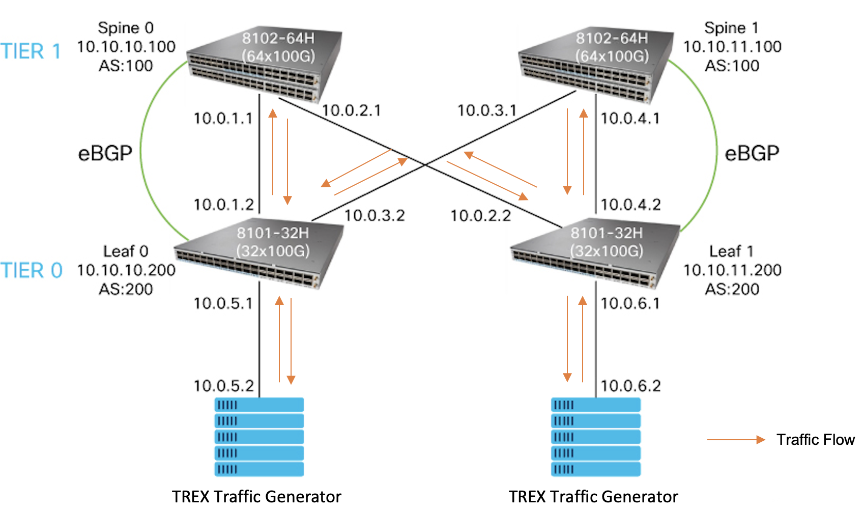
Send Traffic from TREX
TREX is a software traffic generator that runs on Linux.
To simulate server-to-server traffic flow across the 3-stage Clos network, connect the TREX software traffic generator ports as the end-hosts to LEAF0 and LEAF1.
Configure the traffic stream to be injected into LEAF0 from TREX with these parameters:
- Source IP address: 10.0.5.2
- Destination IP address: 10.0.6.2
Configure the traffic stream to be injected into LEAF1 from TREX with these parameters:
- Source IP address: 10.0.6.2
- Destination IP address: 10.0.5.2
To configure the traffic streams, create a yaml file on the TREX server in the location: /opt/cisco/trex/latest/cap2/test-new.yaml. Update the file contents as follows:
- duration : 0.5
  generator :
          distribution : "seq"
          clients_start : "10.0.6.2"
          clients_end   : "10.0.6.2"
          servers_start : "10.0.5.2"
          servers_end   : "10.0.5.2"
          clients_per_gb : 201
          min_clients    : 101
          dual_port_mask : "1.0.0.0"
          tcp_aging      : 0
          udp_aging      : 0
  cap_ipg    : true
  cap_info :
     - name: avl/citrix_0.pcap
       cps : 1.0
       ipg : 10000
       rtt : 10000
       w   : 5
To send a traffic burst from TREX, use the command: ./t-rex-64 -f <traffic_yaml> -m <multiplier> -d <duration> -l <latency test rate> -c <cores>.
Check the Total-tx-pkt and Total-rx-pkt in the summary stats at the end of the TREX output to ensure the number of total transmitted and total received packets are same.
[root@localhost ~]# cd /opt/cisco/trex/latest/
[root@localhost ~]# ./t-rex-64 -f cap2/test-new.yaml -m 300 -d 1
/usr/bin/python3 dpdk_nic_bind.py --bind=igb_uio 0000:00:04.0 0000:00:05.0
The ports are bound/configured.
Starting  TRex v2.97 please wait  ...
 set driver name net_virtio
 driver capability  : SLRO
 set dpdk queues mode to ONE_QUE
 Number of ports found: 2
zmq publisher at: tcp://*:4500
 wait 1 sec .
port : 0
------------
link         :  link : Link Up - speed 100000 Mbps - half-duplex

promiscuous  : 0
port : 1
------------
link         :  link : Link Up - speed 100000 Mbps - half-duplex

promiscuous  : 0
 number of ports         : 2
 max cores for 2 ports   : 1
 tx queues per port      : 3
 .......
 .......
 .......
 summary stats
 --------------
 Total-pkt-drop       : 0 pkts
 Total-tx-bytes       : 25692300 bytes
 Total-tx-sw-bytes    : 0 bytes
 Total-rx-bytes       : 25692300 byte

 Total-tx-pkt         : 81600 pkts <<<<<
 Total-rx-pkt         : 81600 pkts <<<<<
 Total-sw-tx-pkt      : 0 pkts
 Total-sw-err         : 0 pkts
 Total ARP sent       : 4 pkts
 Total ARP received   : 2 pkts
Verify Interface Counters on SONiC Routers
Check the interface counters on the SONiC routers using the command show interface counters rif. Ensure that the traffic sent and received is similar to the stats in the traffic generator output.
You have now successfully brought up a simple 3-stage Clos network, and sent traffic across it, which forms the IP-BGP underlay for your data center network.
You can scale up these configurations as per the number of devices in your data center. The next step is to configure an overlay. Continue to the next section to configure static VXLAN overlay over the 3-stage Clos network.
Configure Static VXLANs over the 3-Stage Clos Network
In this section , the notebook demostrates how to configure static VXLAN tunnels between LEAF0 and LEAF1. The underlay consists of the 3-stage Clos network which we configured in the previous section.
Configure VLAN on Leaf Routers
Configure VLAN 10 on both LEAF routers to set up VXLAN Tunnels between the VLAN segments on the LEAFs. Then remove the IP addresses assigned to the LEAF interfaces connected to the traffic generator and assign the VLAN 10. Assign the IP address that we removed to the VLAN interface.
cisco@LEAF0:~$ sudo config vlan add 10
cisco@LEAF0:~$ sudo config interface ip remove Ethernet2 10.0.5.1/24
cisco@LEAF0:~$ sudo config vlan member add -u 10 Ethernet2
cisco@LEAF0:~$ sudo config interface ip add Vlan10 10.0.5.1/24
cisco@LEAF0:~$ show vlan brief
+-----------+--------------+-----------+----------------+-----------------------+-------------+
|   VLAN ID | IP Address   | Ports     | Port Tagging   | DHCP Helper Address   | Proxy ARP   |
+===========+==============+===========+================+=======================+=============+
|        10 | 10.0.5.1/24  | Ethernet2 | untagged       |                       | disabled    |
+-----------+--------------+-----------+----------------+-----------------------+-------------+
cisco@LEAF1:~$ sudo config vlan add 10
cisco@LEAF1:~$ sudo config interface ip remove Ethernet2 10.0.6.1/24
cisco@LEAF1:~$ sudo config vlan member add -u 10 Ethernet2
cisco@LEAF1:~$ sudo config interface ip add Vlan10 10.0.6.1/24
cisco@LEAF1:~$ show vlan brief
+-----------+--------------+-----------+----------------+-----------------------+-------------+
|   VLAN ID | IP Address   | Ports     | Port Tagging   | DHCP Helper Address   | Proxy ARP   |
+===========+==============+===========+================+=======================+=============+
|        10 | 10.0.6.1/24  | Ethernet2 | untagged       |                       | disabled    |
+-----------+--------------+-----------+----------------+-----------------------+-------------+
Set Up and Apply Static VXLAN Configurations
Static VXLAN configurations are applied using JSON files. This step creates the files with the VXLAN configurations and loads them on LEAF0 and LEAF1. It configures VXLAN with a Virtual Network Identifier (VNI) of 1000 on LEAF0. The source IP address of the tunnel is the IP address of the Loopback 0 interface of LEAF0. This VXLAN maps VLAN 10 with a VNI of 1000.
Like LEAF0, on LEAF1 configure VXLAN with a VNI of 1000, which maps to VLAN 10. The source IP address of the VXLAN tunnel is the IP address of the Loopback0 interface of LEAF1.
cisco@LEAF0:~$ sudo vi VXLAN.json
{
    "VXLAN_TUNNEL": {
        "tunnel_v4": {
            "src_ip": "10.10.10.200"
        }
    },
    "VNET": {
        "Vnet_1000": {
            "vxlan_tunnel": "tunnel_v4",
            "vni": "1000",
            "scope": "default"
        }
    },
    "VLAN_INTERFACE": {
        "Vlan10": {
            "vnet_name": "Vnet_1000",
            "vni": "1000"
        },
        "Vlan10|10.0.5.1/24": {}
    }
}
cisco@LEAF0:~$ sudo config load VXLAN.json -y
Running command: /usr/local/bin/sonic-cfggen -j VXLAN.json --write-to-db
cisco@LEAF0:~$ sudo config save -y
Running command: /usr/local/bin/sonic-cfggen -d --print-data > /etc/sonic/config_db.json
cisco@LEAF1:~$ sudo vi VXLAN2.json
{
    "VXLAN_TUNNEL": {
        "tunnel_v4": {
            "src_ip": "10.10.11.200"
        }
    },
    "VNET": {
        "Vnet_1000": {
            "vxlan_tunnel": "tunnel_v4",
            "vni": "1000",
            "scope": "default"
        }
    },
    "VLAN_INTERFACE": {
        "Vlan10": {
            "vnet_name": "Vnet_1000",
            "vni": "1000"
        },
        "Vlan10|10.0.6.1/24": {}
    }
}
cisco@LEAF1:~$ sudo config load VXLAN2.json -y
Running command: /usr/local/bin/sonic-cfggen -j VXLAN2.json --write-to-db
cisco@LEAF1:~$ sudo config save -y
Running command: /usr/local/bin/sonic-cfggen -d --print-data > /etc/sonic/config_db.json
Set Up and Load VNet Route Tables
Since static VXLAN does not have a control plane to learn routes, set up the route tables manually by playing the below cell, SONiC uses the SWitch State Service (SWSS) docker container to maintain the database of routes. This cell sets up the JSON file for the Virtual Network (VNet) route table and copies it to the SWSS container using the docker cp command. The tables are then loaded in the SWSS container using the docker exec -i swss swssconfig command.
cisco@LEAF0:~$ sudo vi vnt.route_snhop.json
[
    {
        "VNET_ROUTE_TUNNEL_TABLE:Vnet_1000:10.0.6.0/24": {
            "endpoint": "10.10.11.200"
        },
        "OP": "SET"
    },
    {
        "VNET_ROUTE_TUNNEL_TABLE:Vnet_1000:10.0.5.2/32": {
            "ifname": "Vlan10"
        },
        "OP": "SET"
    }
]
cisco@LEAF0:~$ docker cp vnt.route_snhop.json swss://.
cisco@LEAF0:~$ docker exec -i swss swssconfig vnt.route_snhop.json
cisco@LEAF1:~$ sudo vi vnt.route_snhop.json
[
    {
        "VNET_ROUTE_TUNNEL_TABLE:Vnet_1000:10.0.5.0/24": {
            "endpoint": "10.10.10.200"
        },
        "OP": "SET"
    },
    {
        "VNET_ROUTE_TUNNEL_TABLE:Vnet_1000:10.0.6.2/32": {
            "ifname": "Vlan10"
        },
        "OP": "SET"
    }
]
cisco@LEAF1:~$ docker cp vnt.route_snhop.json swss://.
cisco@LEAF1:~$ docker exec -i swss swssconfig vnt.route_snhop.json
Verify Static VXLAN Tunnels
Execute show commands on LEAF routers to check the VXLAN configurations.
cisco@LEAF0:~$ show vxlan interface
VTEP Information:

    VTEP Name : tunnel_v4, SIP  : 10.10.10.200
    Source interface  : Loopback0
cisco@LEAF0:~$ show vnet brief
vnet name    vxlan tunnel      vni  peer list
-----------  --------------  -----  -----------
Vnet_1000    tunnel_v4        1000
cisco@LEAF0:~$ show vnet name Vnet_1000
vnet name    vxlan tunnel      vni  peer list
-----------  --------------  -----  -----------
Vnet_1000    tunnel_v4        1000
cisco@LEAF0:~$ show vnet route all
vnet name    prefix    nexthop    interface
-----------  --------  ---------  -----------

vnet name    prefix       endpoint      mac address    vni
-----------  -----------  ------------  -------------  -----
Vnet_1000    10.0.5.2/32
Vnet_1000    10.0.6.0/24  10.10.11.200
cisco@LEAF0:~$ show mac
  No.    Vlan  MacAddress         Port       Type
-----  ------  -----------------  ---------  -------
    1      10  02:90:E1:3D:38:62  Ethernet2  Dynamic
Total number of entries 1
cisco@LEAF0:~$
cisco@LEAF1:~$ show vxlan interface
VTEP Information:

    VTEP Name : tunnel_v4, SIP  : 10.10.11.200
    Source interface  : Loopback0
cisco@LEAF1:~$ show vnet brief
vnet name    vxlan tunnel      vni  peer list
-----------  --------------  -----  -----------
Vnet_1000    tunnel_v4        1000
cisco@LEAF1:~$ show vnet name Vnet_1000
vnet name    vxlan tunnel      vni  peer list
-----------  --------------  -----  -----------
Vnet_1000    tunnel_v4        1000
cisco@LEAF1:~$ show vnet route all
vnet name    prefix    nexthop    interface
-----------  --------  ---------  -----------

vnet name    prefix       endpoint      mac address    vni
-----------  -----------  ------------  -------------  -----
Vnet_1000    10.0.5.0/24  10.10.10.200
Vnet_1000    10.0.6.2/32
cisco@LEAF1:~$ show mac
  No.    Vlan  MacAddress         Port       Type
-----  ------  -----------------  ---------  -------
    1      10  02:F4:22:26:F3:9D  Ethernet2  Dynamic
Total number of entries 1
Send Traffic across VXLAN Tunnel
To simulate server-to-server traffic flow across VXLAN tunnel, connect the TREX software traffic generator ports as the end-hosts to LEAF0 and LEAF1.
Details of traffic stream injected into LEAF0 from TREX:
- Source IP address: 10.0.5.2
- Destination IP address: 10.0.6.2
Details of traffic stream injected into LEAF1 from TREX:
- Source IP address: 10.0.6.2
- Destination IP address: 10.0.5.2
To send a traffic burst from TREX, use the command: ./t-rex-64 -f <traffic_yaml> -m <multiplier> -d <duration> -l <latency test rate> -c <cores>, as shown below. Check the Total-tx-pkt and Total-rx-pkt in the summary stats at the end of the TREX output to ensure that the number of total transmitted and total received packets are same.
[root@localhost ~]# cd /opt/cisco/trex/latest/
[root@localhost ~]# ./t-rex-64 -f cap2/test-new.yaml -m 300 -d 1
/usr/bin/python3 dpdk_nic_bind.py --bind=igb_uio 0000:00:04.0 0000:00:05.0
The ports are bound/configured.
Starting  TRex v2.97 please wait  ...
 set driver name net_virtio
 driver capability  : SLRO
 set dpdk queues mode to ONE_QUE
 Number of ports found: 2
zmq publisher at: tcp://*:4500
 wait 1 sec .
port : 0
------------
link         :  link : Link Up - speed 100000 Mbps - half-duplex

promiscuous  : 0
port : 1
------------
link         :  link : Link Up - speed 100000 Mbps - half-duplex

promiscuous  : 0
 number of ports         : 2
 max cores for 2 ports   : 1
 tx queues per port      : 3
 .......
 .......
 .......
 summary stats
 --------------
 Total-pkt-drop       : 0 pkts
 Total-tx-bytes       : 25692300 bytes
 Total-tx-sw-bytes    : 0 bytes
 Total-rx-bytes       : 25692300 byte

 Total-tx-pkt         : 81600 pkts <<<<<
 Total-rx-pkt         : 81600 pkts <<<<<
 Total-sw-tx-pkt      : 0 pkts
 Total-sw-err         : 0 pkts
 Total ARP sent       : 4 pkts
 Total ARP received   : 2 pkts
Tested Static VXLAN Scale
A scale of 32K remote Virtual Tunnel End Points (VTEP) with 128K unique overlay-prefix and VTEP Encap entries has been demonstrated on Cisco 8000 routers with SONiC. For more details of this demo by the Cisco team, refer https://blogs.cisco.com/sp/cisco-and-sonic
Try out this use case on Interactive Python Notebooks
Try out this use case and more even without the Cisco 8000 router hardware. This Learning Lab helps you execute use cases and configurations on SONiC on Cisco 8000.
In this Learning Lab, we've created three SONiC-based configuration examples that demonstrate how to:
Setup a 3-Stage Clos Network
Configure a 3 Stage Clos Network with Static VXLAN
Configure a 3 Stage Clos Network with Port Channels
Contact us at sonic-8000-docs@cisco.com for feedback or queries about this use case.