VXLAN EVPN
VXLAN EVPN is a network overlay solution that
uses Virtual Extensible LAN (VXLAN) as the data plane to extend Layer 2 segments across a Layer 3 underlay
utilizes Ethernet VPN (EVPN) as the control plane for dynamic learning and distribution of MAC and IP reachability information, and
enables network devices to operate as VXLAN Tunnel Endpoints (VTEPs), providing scalable and flexible overlay services.
Key concepts of VXLAN EVPN
VXLAN
Virtual Extensible LAN (VXLAN) is a network virtualization technology that provides Layer 2 connectivity across a Layer 3 network. It encapsulates Ethernet frames within UDP packets for tunneling and utilizes a 24-bit VXLAN Network Identifier (VNID), supporting high scalability.
VXLAN terminology
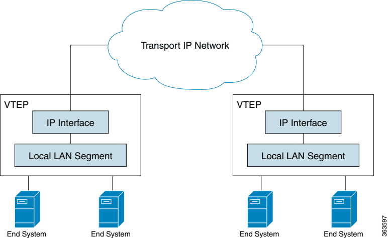
- VXLAN Tunnel Endpoint (VTEP): A VTEP is a network device that connects local LAN segments to the VXLAN overlay network by encapsulating and deencapsulating Ethernet frames into VXLAN packets, which are transported over UDP and IP. Each VTEP has a unique IP address, typically assigned to a loopback interface, that identifies it within the transport IP network and serves as the source address for encapsulated VXLAN packets. VTEPs also map local MAC addresses to VXLAN segments, learn remote MAC-to-VTEP mappings, and communicate with other VTEPs to enable seamless Layer 2 connectivity across the IP-based transport network. This figure shows the functional components of VTEPs and the logical topology that is created for Layer 2 connectivity across the transport IP network.
VXLAN Tunnel: The logical path created between two VTEPs over the Layer 3 underlay network, through which encapsulated VXLAN packets travel.
Underlay Network: The physical Layer 3 IP network that provides connectivity between VTEPs. It is responsible for routing the encapsulated VXLAN packets.
Overlay Network: The logical Layer 2 network created by VXLAN, which spans across the Layer 3 underlay.
VRF VLAN: A VRF VLAN is a dedicated VLAN, along with its associated VNI, configured for each Virtual Routing and Forwarding (VRF) instance. It is used to enable inter-VLAN routing within a specific VRF. You should use the same VRF VLAN ID and VNI on all leaf switches where this VRF is present.
PortChannel: A PortChannel, also known as a Link Aggregation Group (LAG), is a logical interface that combines multiple physical Ethernet links between an end host or server and one or more VXLAN Tunnel Endpoints (VTEPs), typically leaf switches. This aggregation provides the host with a single, high-bandwidth, and resilient connection. In the EVPN control plane, the PortChannel is identified as an Ethernet Segment (ES), with an Ethernet Segment Identifier (ESI) configured on the PortChannel to indicate that multiple VTEPs are connected to the same multi-homed device. PortChannels are essential for VXLAN EVPN deployments, enabling robust All-Active multi-homing.
VXLAN packet format
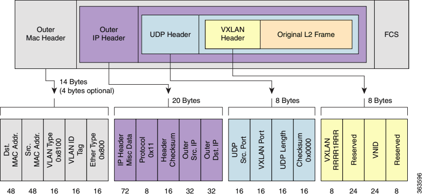
VXLAN defines a MAC-in-UDP encapsulation scheme in which the original Layer 2 frame has a VXLAN header added and is then placed in a UDP/IP packet. With this MAC-in-UDP encapsulation, VXLAN tunnels a Layer 2 network over a Layer 3 network. This figure shows the VXLAN packet format.
EVPN
Ethernet VPN (EVPN) is a control plane protocol that leverages Border Gateway Protocol (BGP) to exchange MAC addresses, IP addresses, and other Layer 2 and Layer 3 reachability information between VTEPs.
It enables dynamic learning of endpoint information, eliminates the need for data plane flooding, and supports advanced features such as multi-homing and distributed anycast gateways. EVPN supports All-Active multi-homing mode to provide redundancy and load balancing.
EVPN terminology
Ethernet segment (ES): A logical construct representing a set of Ethernet links that connect a host to one or more leaf switches, which act as VTEPs within the data center.
Ethernet segment identifier (ESI): A unique 10-octet identifier assigned to an ES. All leaf switches connected to the same ES must use the same ESI. ESI is optional for single-homing and mandatory for multi-homing.
Multi-homing: The ability for a host or server to connect simultaneously to multiple leaf switches for redundancy and load balancing. Supports Active-Active multi-homing mode.
All-Active multi-homing: All leaf switches connected to the ES can actively forward unicast traffic to and from the host or server, enabling load balancing and faster convergence.
Designated Forwarder (DF): In multi-homing scenarios—where a host or server is connected to multiple leaf switches via an ES—the DF is the single leaf switch elected to forward broadcast, unknown-unicast, and multicast (BUM) traffic from the multihomed ES into the EVPN network. This election prevents BUM traffic duplication. Non-DF leaf switches block BUM traffic from the ESI.
EVPN instance (EVI): A logical VPN instance within an EVPN domain that provides Layer 2 connectivity for a specific set of end systems. Each EVI is typically associated with one or more VNIDs and has its own set of route distinguishers (RDs) and route targets (RTs).
L2VPN EVPN address family: A specific BGP address family used to carry EVPN routes. BGP is extended to transport MAC and IP reachability information for virtual networks, enabling EVPN as the control plane for VXLAN. Configuring address-family l2vpn evpn in BGP allows the exchange of these specialized EVPN routes for dynamic endpoint learning and distribution across the data center network.
EVPN route types
EVPN Route Types (RTs) are BGP message types that are used by the EVPN control plane to signal different types of information and enable dynamic learning and distribution of network reachability information.
The EVPN control plane uses various BGP EVPN Route Types (RTs) to signal different types of information.
| Route type | Signaling/Advertisement | Purpose |
|---|---|---|
| RT1 (Ethernet Auto-Discovery Route per ESI) | Signaled per ESI | Allows remote leaf switches to determine how to load balance unicast traffic to a multihomed segment |
| RT2 (MAC/IP Advertisement Route) | Advertises MAC addresses and optionally IP addresses of endpoints | Enables VTEPs on leaf to learn remote MACs and IPs, and to program their forwarding tables |
| RT3 (Inclusive Multicast Ethernet Tag Route) | Signals information for BUM traffic replication | Ensures efficient delivery of BUM traffic across the VXLAN overlay |
| RT4 (Ethernet Segment Route) | Used for DF election for multihomed segments | Prevents duplicate BUM traffic by ensuring only the DF-elected leaf switch forwards such traffic |
| RT5 (IP Prefix Route) | Advertises IP prefixes for inter-subnet routing within the EVPN domain | Used in distributed anycast gateway scenarios for advertising host routes or subnet routes |
EVPN distributed anycast gateway
EVPN distributed anycast gateway is a Layer 3 gateway solution in which multiple VTEPs are configured with the same IP address and MAC address for a specific VLAN or VNI. This allows the VTEPs to operate as a single logical Layer 3 gateway, enabling active-active forwarding, high availability, and efficient load distribution for inter-subnet traffic.
Key benefits of VXLAN EVPN
- Scalability: BGP EVPN provides a highly scalable control plane for MAC and IP address learning, eliminating the need for traditional flooding-based learning.
- Flexibility: Supports both Layer 2 (L2VNI) and Layer 3 (L3VNI) services, allowing for efficient inter-subnet routing and multi-tenancy.
- Resilience: Multi-homing capabilities provide redundancy and load balancing for attached devices. We support only Active-Active multi-homing mode.
- Openness: SONiC, being an open-source network operating system, leverages standard protocols for VXLAN EVPN implementation.
Example VXLAN EVPN topology and workflow
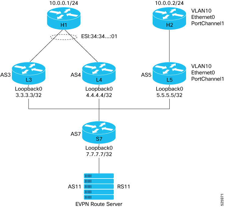
This process describes how data packets are handled using VXLAN for data plane encapsulation and BGP EVPN for control plane signaling. The leaf switches support multihomed host H1 to L3 and L4, and host H2 connected to L5. An EVPN Route Server (RS11) manages the control plane, ensuring resilient and efficient traffic handling for various traffic types across the network.
The key components involved in the VxLAN EVPN process are:
Leaf switches (L3, L4, L5): These switches connect to hosts and perform local MAC/IP learning, VXLAN encapsulation/decapsulation, and route advertisement. Host H1 connects to leaf L3 and L4. Host H2 connects to leaf L5.
EVPN Route Server (RS11): This server receives and reflects BGP EVPN routes, enabling network-wide host and segment reachability.
Host H1: A multihomed host connected to leaf L3 and leaf L4.
Host H2: A host connected to L5.
IP Fabric: The underlying network that transports encapsulated VXLAN packets.
Topology
The VXLAN EVPN process uses BGP EVPN signaling to distribute host and network segment information across leaf L3, leaf L4, and leaf L5. It involves local MAC learning by the leaf, route advertisement to and reflection by RS11, VXLAN encapsulation, forwarding, and decapsulation, and specific handling for flooded traffic to ensure optimal network performance and resilience.
Workflow
These stages describe how traffic flows through the VXLAN with EVPN All-Active multi-homing topology.
Host connection and local MAC learning
- Leaf L3 and L4 learn H1's MAC address, and for Layer 3 traffic, they learn its IP address.
- Leaf L5 learns H2's MAC address and, for Layer 3 traffic, its IP address.
BGP EVPN route advertisement
- Leaf L3 and L4 advertise H1's host and segment information via BGP EVPN to RS11, including:
- routes (BGP EVPN Route Type 1): For H1's multi-homing details (ESI, All-Active type).
- MAC/IP Advertisement routes (BGP EVPN Route Type 2): For H1's MAC and IP addresses.
- Inclusive Multicast Ethernet Tag routes (BGP EVPN Route Type 3): For BUM traffic originating from H1.
- L5 advertises:
- H2's host information (MAC/IP via RT2).
- BUM information (via RT3) to RS11.
- RS11 receives these BGP EVPN routes and reflects them to leaf L3, leaf L4, and leaf L5.
- Leaf L3 and L4 advertise H1's host and segment information via BGP EVPN to RS11, including:
Designated Forwarder election
- Leaf L3 and L4 elect a DF for H1's multihomed connection using BGP EVPN Route Type 4 signaling.
- The elected DF forwards BUM traffic originating from H1 to the VXLAN overlay.
- The non-DF leaf drops BUM traffic from H1 for that ESI to prevent packet duplication.
a. Downstream traffic (Leaf to H1): - Leaf L3 and L4 use BGP EVPN Route Type 4 signaling to elect a DF for H1’s multihomed connection. - The elected DF is responsible for forwarding BUM traffic from the VXLAN overlay to H1. - The non-DF leaf drops BUM traffic for H1 to prevent duplication.
b. Upstream traffic (H1 to Leaf): - DF election is not relevant for traffic sent by H1 towards the network. - H1’s hashing algorithm selects only one uplink (one leaf) for each flow, so only that leaf receives H1's upstream traffic.
VXLAN encapsulation, forwarding, and de-encapsulation
- When H1 sends traffic destined for H2, the packet arrives at either leaf L3 or L4.
- Leaf L3 performs a lookup for H2's MAC address and, based on learned routes from RS11, determines H2 is reachable via L5.
- Leaf L3 encapsulates the original Ethernet frame or IP packet into a VXLAN packet:
- Adds a VXLAN header and an outer IP/UDP header destined for L5's VTEP IP address.
- The VXLAN VNI in the VXLAN header is found from the VLAN-VNI mapping.
- The encapsulated VXLAN packet is forwarded across underlying IP Fabric to L5.
- L5 receives the VXLAN packet, decapsulates it by removing the outer headers, and delivers the original packet to H2 or routes it to its next hop.
Distributed anycast gateway functionality
- Host H1 sends Layer 3 traffic destined outside its local subnet to a common Anycast Gateway IP address.
- Leaf L3 and L4, configured as part of the distributed anycast gateway, respond to ARP requests for this gateway IP with the same MAC address.
- The leaf receiving the packet performs local routing within the appropriate VRF instance.
- The leaf encapsulates the Layer 3 traffic across the VXLAN overlay, potentially to L5 if it is an egress point to an external network.
- The VXLAN VNI in the VXLAN header is found from the VRF-VNI mapping (from one VLAN to another, or from one VLAN to an external prefix).
- For inter-VLAN routing within a VRF, especially in asymmetric IRB scenarios where not all VLANs are present on every leaf, a dedicated VRF VLAN and its corresponding VNI are used. This VRF VNI (e.g., VNI 9900 for Vlan900) is used to encapsulate traffic between the ingress and egress VTEPs when routing between different VLANs within the same VRF. The egress VTEP then receives the packet with the VRF VNI, performs a destination lookup within the VRF, and inserts the packet into the locally configured destination VLAN.
Configure VXLAN EVPN on SONiC
Complete this task to configure and verify VXLAN EVPN All-Active multi-homing for seamless host connectivity, redundancy, and optimal traffic flow in a multi-leaf network fabric.
Configuring VXLAN EVPN on SONiC involves the following steps:
- Configure the underlay network
- Configure BGP L2VPN EVPN
- Configure VRF and VNI for Distributed Anycast Gateway
- Configure VLAN Layer 2 and 3
- Attach a VLAN to an interface
Before you begin
Ensure that these prerequisites are met:
- SONiC switches are running a version that supports VXLAN EVPN features.
- A fully routed IP network that provides IP reachability between all VTEP loopback interfaces.
- Each VTEP must have a dedicated loopback interface configured with an IP address, which will serve as the VXLAN tunnel source IP. This IP must be reachable across the underlay.
- If using BGP as the underlay routing protocol, ensure BGP peering is established between leaf and spine switches.
- Access ports and uplink ports should be configured appropriately.
Configure underlay network
This section provides the configuration and verification of the underlying Layer 3 network that provides connectivity between VTEPs.
Follow these steps to configure underlay:
- First, let's configure the underlay network. Assign a loopback address and IP addresses either IPv4 or IPv6 on all underlay
interfaces between leaf and spine devices using the
configure interface ip addcommand.
Here is an example of the leaf L3 configuration. The loopback address of leaf L3 is 3.3.3.3/32 and the IP address of the Ethernet40 interface is 3.7.1.3/24.
config interface ip add Loopback0 3.3.3.3/32
config interface ip add Ethernet40 3.7.1.3/24
Verify the configured IP addresses by using the
show ip interfacecommand. Ensure the interfaces are up.Here is an example of the show output for leaf L3.
admin@Leaf-3: show ip interface
Interface    Master    IPv4 address/mask    Admin/Oper    BGP Neighbor    Neighbor IP
------  --------  -------------------  ------------  --------------  -------------
Ethernet40         3.7.1.3/24                up/up         N/A             N/A
Loopback0          3.3.3.3/32                up/up         N/A             N/A
docker0            240.127.1.1/24            up/down       N/A             N/A
eth0               192.168.122.203/24        up/up         N/A             N/A
eth4               192.168.123.61/24         up/up         N/A             N/A
lo                 127.0.0.1/16              up/up         N/A             N/A
- Configure BGP between the leaf switches and spine devices to form the underlay network.
In this example, 3.7.1.7 is the address of the spine on the interface connecting the leaf and spine. In this example, eBGP is established with the spine, as AS number 3 is configured on the leaf, and AS number 7 is configured on the spine.
These BGP configuration are commonly used to modify default BGP behavior.
no bgp ebgp-requires-policy: This command disables the default requirement for explicit route policies on eBGP peers, simplifying configuration in a trusted underlay.no bgp default ipv4-unicast: This command forces explicit activation of the IPv4 unicast address family, enabling modular configuration for MP-BGP deployments like EVPN.bgp bestpath as-path multipath-relax: This command help relax eBGP multipath requirements to allow ECMP load balancing across spines with different AS numbers but same AS path length.
router bgp 3
 bgp router-id 3.3.3.3
 no bgp ebgp-requires-policy
 no bgp default ipv4-unicast
 bgp bestpath as-path multipath-relax
 neighbor 3.7.1.7 remote-as 7
 !
 address-family ipv4 unicast
  redistribute connected route-map loopback
  neighbor 3.7.1.7 activate
 exit-address-family
 !
ip prefix-list loopback seq 5 permit 0.0.0.0/0 ge 32
!
route-map loopback permit 10
 match ip address prefix-list loopback
exit
- Verify the eBGP peering sessions established between leaf and spine. These commands confirm that BGP peering sessions are successfully established and that the expected routes, such as loopback addresses of other VTEPs, are being learned.
a. Use the show bgp ipv4 unicast summary command to view the summary of the BGP session status and IPv4 unicast peers.
Leaf-3# show bgp ipv4 unicast summary
BGP router identifier 3.3.3.3, local AS number 3 vrf-id 0
……
Neighbor        V         AS     MsgRcvd   MsgSent   TblVer  InQ OutQ  Up/Down State/PfxRcd   PfxSnt       Desc
3.7.1.7         4          7      8169      8169        0    0    0            5d16h01m            4        5 N/A
b. The loopbacks of the other switches learned from the spine.
Leaf-3#show bgp ipv4 unicast
BGP table version is 7, local router ID is 3.3.3.3, vrf id 0
Default local pref 100, local AS 3
Status codes:  s suppressed, d damped, h history, * valid, > best, = multipath,
               i internal, r RIB-failure, S Stale, R Removed
Nexthop codes: @NNN nexthop's vrf id, < announce-nh-self
Origin codes:  i - IGP, e - EGP, ? - incomplete
RPKI validation codes: V valid, I invalid, N Not found
    Network          Next Hop            Metric LocPrf Weight Path
 *> 3.3.3.3/32       0.0.0.0                  0         32768
 *> 4.4.4.4/32    3.7.1.7                                  0 7 4
 *> 5.5.5.5/32       3.7.1.7                              0 7 5
*> 7.7.7.7/32       3.7.1.7                  0            0 7
*> 11.11.11.11/32   3.7.1.7                               0 7 1 1
In this example, the loopbacks learned by leaf L3 are:
*> 5.5.5.5/32       3.7.1.7                              0 7 5
*> 7.7.7.7/32       3.7.1.7                  0            0 7
*> 11.11.11.11/32   3.7.1.7                               0 7 1 1
c. Use the show arp command to display the ARP address of the spine as seen by the leaf.
The 'show arp' command verifies Layer 2 reachability by displaying the Address Resolution Protocol (ARP) table. This table maps IP addresses to MAC addresses for devices on the local network segment.
In this example, 3.7.1.7 is the ARP address of the spine as seen by the leaf.
admin@Leaf-3: show arp
Address                MacAddress            Iface   Vlan
-------------  -----------------             -----   ------
3.7.1.7           78:66: 00:00:80:00          etp10    -
192.168.122.1     7y:00:00:00:ca:00           eth0      -
192.168.123.1     ae:08:00:00:00:00           eth4      -
d. Use the show ip route command to display the routing table on the switch.
In this example, the entry C>*3.3.3.3/32 is directly connected. The interface Ethernet40 is the underlay interface that connects the leaf switch to the spine.
Leaf-3# show ip route
Codes: K - kernel route, C - connected, S - static, R - RIP,
O - OSPF, I - IS-IS, B - BGP, E - EIGRP, N - NHRP,
T - Table, v - VNC, V - VNC-Direct, A - Babel, D - SHARP,
F - PBR, f - OpenFabric,
> - selected route, * - FIB route, q - queued route, r - rejected route
K>*0.0.0.0/0 [0/202] via 192.168.122.1, eth0, 01:31:55
C>*3.3.3.3/32 is directly connected, Loopback0, 00:13:02
C>*3.7.1.0/24 is directly connected, Ethernet40, 00:12:54
B>*4.4.4.4/32 [20/0] via 3.7.1.7, Ethernet40, 00:05:38
B>*5.5.5.5/32 [20/0] via 3.7.1.7, Ethernet40, 00:00:10
B>*7.7.7.7/32 [20/0] via 3.7.1.7, Ethernet40, 00:10:28
B>*11.11.11.11/32 [20/0] via 3.7.1.7, Ethernet40, 00:05:21
C>*192.168.122.0/24 is directly connected, eth0, 01:31:55
C>*192.168.123.0/24 is directly connected, eth4, 01:31:55
admin@Leaf-3:~$
Configure BGP L2VPN EVPN
This section covers the foundational BGP EVPN control plane setup, including VXLAN parameters and BGP peering for EVPN route exchange, independent of specific VLANs or VNIs. These configurations will be used across different L2VNI/L3VNI and single homing or multihoning scenarios.
Follow these steps to configure BGP L2VPN EVPN:
- Configure the VTEP tunnel interface to define the VXLAN encapsulation parameters. These configurations define the VTEP tunnel interface to establish VXLAN encapsulation parameters and integrate it with an EVPN Network Virtualization Overlay (NVO):
config vxlan add VXLAN 3.3.3.3
config vxlan evpn_nvo add NVO VXLAN
- On each leaf, configure BGP to enable the L2VPN EVPN address family and establish peering with the Route Server (RS11). This setup enables the dynamic exchange of EVPN route types (RT-1, RT-2, RT-3, RT-4).
VNI advertisements can be selectively controlled by applying BGP route-maps to the address-family l2vpn evpn neighbor configuration. You can use the advertise-all-vni command to simplify configuration and provide comprehensive VNI visibility across a trusted fabric.
router bgp 3
 bgp router-id 3.3.3.3
 no bgp ebgp-requires-policy
 no bgp default ipv4-unicast
 bgp bestpath as-path multipath-relax
 neighbor evpn peer-group
 neighbor evpn ebgp-multihop 10
 neighbor evpn disable-connected-check
 neighbor evpn update-source Loopback0
 neighbor 11.11.11.11 remote-as 11
 neighbor 11.11.11.11 peer-group evpn
 neighbor 3.7.1.7 remote-as 7
 !
 address-family ipv4 unicast
 !
 address-family l2vpn evpn
  neighbor evpn activate
  advertise-all-vni
exit-address-family
evpn mh redirect-off
- Configure BGP EVPN on the Route Server (RS11).
  router bgp 11
    bgp router-id 11.11.11.11
    no bgp ebgp-requires-policy
    no bgp default ipv4-unicast
    bgp bestpath as-path multipath-relax
    neighbor evpn peer-group
    neighbor evpn ebgp-multihop 10
    neighbor evpn disable-connected-check
    neighbor evpn update-source Loopback0
    neighbor pass peer-group
    neighbor 7.11.1.7 remote-as 7
    neighbor 3.3.3.3 remote-as 3
    neighbor 4.4.4.4 remote-as 4
    neighbor 5.5.5.5 remote-as 5
    neighbor 6.6.6.6 remote-as 6
    neighbor 3.3.3.3 peer-group evpn
    neighbor 4.4.4.4 peer-group evpn
    neighbor 5.5.5.5 peer-group evpn
    neighbor 6.6.6.6 peer-group evpn
 !
address-family l2vpn evpn
 neighbor evpn activate
 neighbor evpn attribute-unchanged as-path next-hop med
exit-address-family
exit
- Verify EVPN control plane configuration.
Use the show bgp l2vpn evpn summary to verify that BGP L2VPN EVPN sessions are up.
Leaf-3# show bgp l2vpn evpn summary
BGP router identifier 3.3.3.3, local AS number 3 vrf-id 0
BGP table version 0
RIB entries 0, using 0 bytes of memory
Peers 1, using 22 KiB of memory
Peer groups 2, using 128 bytes of memory

Neighbor        V         AS   MsgRcvd   MsgSent   TblVer  InQ OutQ  Up/Down State/PfxRcd   PfxSnt Desc
11.11.11.11     4         11       371       372        0    0    0 06:08:18            0        0 N/A

Total number of neighbors 1
Configure VRF and VNI for Distributed Anycast Gateway
Let’s now create a VRF. For Layer 3 traffic between VLANs inside the VRF, assign one unused VLAN number and one unused VNI number to the VRF. You can select these numbers arbitrarily, as long as they are not used by any Layer 2 VLAN or VNI.
Note: L3VNI requires a VRF VLAN to act as a bridge between the control plane and the forwarding plane.
config vlan add 900
config vrf add Vrfa
config interface vrf bind Vlan900 Vrfa

config vxlan map add VXLAN 900 9900
config vrf add_vrf_vni_map Vrfa 9900

config static-anycast-gateway mac_address add 0a:aa:aa:aa:aa:aa
Similarly, let’s add the FRR configuration to set up BGP EVPN and VRF settings that support VXLAN-based Layer 2 and Layer 3 forwarding. The vni 9900 configuration within the vrf Vrfa block in FRR explicitly informs the BGP EVPN control plane about the association between VRF Vrfa and VNI 9900. This is crucial for BGP to correctly advertise and process EVPN routes (such as Type 5 IP Prefix routes) related to this VRF, ensuring proper Layer 3 forwarding and reachability within the EVPN domain.
router bgp 3
 address-family l2vpn evpn
  advertise ipv4 unicast
  no use-es-l3nhg
 exit-address-family
exit

vrf Vrfa
 vni 9900
exit-vrf

router bgp 3 vrf Vrfa
 bgp router-id 3.3.3.3
 bgp bestpath as-path multipath-relax
 !
 address-family ipv4 unicast
  redistribute connected
  rt vpn both 9900:9900
 exit-address-family
 !
 address-family l2vpn evpn
  no use-es-l3nhg
  advertise ipv4 unicast
  route-target import 9900:9900
  route-target export 9900:9900
 exit-address-family
exit
Configure VLAN Layer 2 and 3
This section provides the configuration for integrating VLANs into the VXLAN EVPN fabric, covering different scenarios. Note: Repeat the steps for each VLAN that needs to be configured.
In this example, we will configure VLAN 10 and its associated VNI 1010. The VNI number is used in the VXLAN header and is an arbitrary chosen value that must be unique. There is a one-to-one mapping between the VLAN number and the VNI number.
- Create the VLAN, VTEP, and VNI on the leaf switches, and advertise them in BGP.
config vlan add 10
config vxlan map add VXLAN 10 1010
config interface vrf bind Vlan10 Vrfa
config interface ip add Vlan10 10.0.0.250/24
config vlan static-anycast-gateway enable 10
Here is the FRR configuration to advertise VLAN, VTEP, and VNI that we created.
router bgp 3
address-family l2vpn evpn
 vni 1010
  route-target import 1010:1010
  route-target export 1010:1010
 exit-vni
exit-address-family
- Verify that VLANs are correctly mapped to their respective VNIs and that VXLAN tunnels to remote VTEPs are operational.
In this example, VLAN 10 is mapped to VNI 1010, and VXLAN tunnels to remote VTEPs (such as 3.3.3.3 and 4.4.4.4) are operational.
admin@Leaf-5:~$show vxlan tunnel
vxlan tunnel name    source ip    destination ip    tunnel map name    tunnel map mapping(vni -> vlan)
-------------------  -----------  ----------------  -----------------  ---------------------------------
VXLAN                5.5.5.5                                    map_1010_Vlan10    1010 -> Vlan10
                                                                            map_9900_Vlan900   9900 -> Vlan900

admin@Leaf-5:~show vxlan vlanvnimap
+---------+-------+
| VLAN    |   VNI |
+=========+=======+
| Vlan10  |  1010 |
+---------+-------+
| Vlan900 |  9900 |
+---------+-------+
Attach a VLAN to an interface
The next step is to attach a VLAN to an interface. There are two options for this:
- Single-homed interface: In this case, you attach the VLAN to an Ethernet interface on one leaf switch. Hosts connected to that Ethernet interface will have non-redundant access to the VLAN.
- Multi-homed attachment circuit: In this case, you configure a PortChannel hosted on two different leaf switches to be part of the VLAN. Hosts connected to that PortChannel will have redundant access to the VLAN through the two interfaces and the two leaf switches.
Configure multi-homed Layer 2 and Layer 3 VLAN
- First step is to configure the PortChannel if it has not been configured yet for a previous VLAN.
Note: Repeat these configurations on both leaf switches where the PortChannel is hosted (Leaf-3 and Leaf-4 in our example):
config portchannel add PortChannel1
config portchannel member add PortChannel1 Ethernet0
config interface evpn-esi add PortChannel1 00:34:34:34:34:34:34:34:34:01
config interface sys-mac add PortChannel1 00:bb:bb:bb:bb:bb
This command is optional if you want to influence the PortChannel Designated Forwarded (df) election:
config interface evpn-df-pref PortChannel1 100
- Configure VLAN on the PortChannel. You can follow one of these two options.
- Use this option if you want the PortChannel to be part of VLAN 10 and use dot1q encapsulation:
config vlan member add 10 PortChannel1
- Use this option for untagged encapsulation on the PortChannel:
config vlan member add 10 PortChannel1 -u
- Verify multi-homed Layer 2 and Layer 3 VLAN configuration.
Use the show evpn es detail and show evpn es to verify EVPN tunnel.
This example is for leaf 5. In this example, L5 has L3 and L4 as next-hops for the PortChannel1 ethernet-segment so Leaf-5 will load balance between L3 and L4.
admin@Leaf-5:~$ show evpn es detail
ESI: 00:34:34:34:34:34:34:34:34:01
 Type: Remote
 Interface: -
 Ready for BGP: no
 VNI Count: 0
 MAC Count: 1
 DF preference: 0
 Nexthop group: 536870913
 VTEPs:
     3.3.3.3 nh: 268435459
     4.4.4.4 nh: 268435458

admin@Leaf-5:~show evpn es
Type: B bypass, L local, R remote, N non-DF
ESI                            Type ES-IF                 VTEPs
00:34:34:34:34:34:34:34:34:01  R    -                     3.3.3.3,4.4.4.4
- Verify BGP L2VPN EVPN tunnel.
In this example, the show bgp l2vpn evpn output confirms the route type as Type 2 for the MAC 78:b4:00:00:00:00. The Mac is advertised by Leaf-3 and it has the ESI of the PortChannel1 so that traffic from L5 will be load balanced between Leaf-3 and Leaf-4.
Leaf-5#show bgp l2vpn evpn
……
   Network          Next Hop            Metric LocPrf Weight Path
Route Distinguisher: 3.3.3.3:2
 *> [1]:[0]:[00:34:34:34:34:34:34:34:34:01]:[32]:[0.0.0.0]:[0]
                    3.3.3.3                                0 3 i
                    RT:1010:1010 ET:8
 *> [2]:[0]:[48]:[78:b4:00:00:00:00]
                    3.3.3.3                                0 3 i
                    ESI:00:34:34:34:34:34:34:34:34:01
                    RT:1010:1010 ET:8
 *> [3]:[0]:[32]:[3.3.3.3]
                    3.3.3.3                                0 3 i
                    RT:1010:1010 ET:8
Route Distinguisher: 3.3.3.3:3
 *> [1]:[4294967295]:[00:34:34:34:34:34:34:34:34:01]:[32]:[0.0.0.0]:[0]
                    3.3.3.3                                0 3 i
                    RT:1010:1010 ET:8 ESI-label-Rt:AA
 *> [4]:[00:34:34:34:34:34:34:34:34:01]:[32]:[3.3.3.3]
                    3.3.3.3                                0 3 i
                    ET:8 ES-Import-Rt:34:34:34:34:34:34 DF: (alg: 2, pref: 32767)

Leaf-5#show bgp l2vpn evpn
……
Route Distinguisher: 5.5.5.5:4
 *> [2]:[0]:[48]:[78:2f:00:00:00:00]
                    5.5.5.5                            32768 i
                    ET:8 RT:1010:1010
 *> [3]:[0]:[32]:[5.5.5.5]
                    5.5.5.5                            32768 i
                    ET:8 RT:1010:1010
In this example, Leaf 5 sees the MAC of Host1 pointing at the Ethernet Segment between L3 and L4. L5 also has a local MAC behind its local interface Ethernet0.
admin@Leaf-5:~$ show mac
  No.    Vlan  MacAddress         Port       Type
-----  ------  -----------------  ---------  -------
    1      10  78:2F:DB:6C:90:00  Ethernet0  Dynamic
    2      10  78:B4:2C:55:D0:00  4.4.4.4    Static
                                  3.3.3.3
Total number of entries 2
Leaf-5# vtysh

Hello, this is FRRouting (version 8.5.4).
Copyright 1996-2005 Kunihiro Ishiguro, et al.

Leaf-5# show evpn mac vni all

VNI 1010 #MACs (local and remote) 2

Flags: N=sync-neighs, I=local-inactive, P=peer-active, X=peer-proxy, L=local
MAC               Type   Flags Intf/Remote ES/VTEP            VLAN  Seq #'s
78:2f:db:6c:90:00 local  L      Ethernet0                      10    1/0
78:b4:2c:55:d0:00 remote        00:34:34:34:34:34:34:34:34:01        0/0
Leaf-5#
- Verify VXlan tunnel and VTEP.
admin@Leaf-5:~$ show vxlan remotevtep
+---------+---------+-------------------+--------------+
| SIP | DIP | Creation Source | OperStatus |
+=========+=========+===================+==============+
| 5.5.5.5 | 3.3.3.3 | EVPN | oper_up |
+---------+---------+-------------------+--------------+
| 5.5.5.5 | 4.4.4.4 | EVPN | oper_up |
+---------+---------+-------------------+--------------+
Total count : 2

admin@Leaf-5:~show vxlan remotemac all
+---------+-------------------+----------------+-------+---------+
| VLAN    | MAC               | RemoteTunnel   |   VNI | Type    |
+=========+===================+================+=======+=========+
| Vlan10  | 78:b4:00:00:00:00 | 3.3.3.3        |  1010 | dynamic |
|         |                   | 4.4.4.4        |       |         |
+---------+-------------------+----------------+-------+---------+

admin@Leaf-5:~show vxlan remotevni all
+--------+--------------+-------+
| VLAN   | RemoteVTEP   |   VNI |
+========+==============+=======+
| Vlan10 | 3.3.3.3      |  1010 |
+--------+--------------+-------+
| Vlan10 | 4.4.4.4      |  1010 |
+--------+--------------+-------+
- Verify the anycast gateway.Use the
show vxlan tunnelcommand to displays the VXLAN tunnel configuration, including the source IP and VNI-to-VLAN mappings.
In this example, VNI 1010 is mapped to Vlan10 and VNI 9900 is mapped to Vlan900 for the tunnel with source IP 5.5.5.5.
admin@Leaf-5:~show vxlan tunnel
vxlan tunnel name    source ip    destination ip    tunnel map name    tunnel map mapping(vni -> vlan)
-------------------  -----------  ----------------  -----------------  ---------------------------------
VXLAN                5.5.5.5                                    map_1010_Vlan10    1010 -> Vlan10
                                                                map_9900_Vlan900   9900 -> Vlan900
Use the ip route show vrf Vrfa command to display the routing table for the VRF Vrfa, showing both directly connected and BGP-learned routes.
admin@Leaf-5:~ip route show vrf Vrfa
10.0.0.0/24 dev Vlan10 proto kernel scope link src 10.0.0.250
10.0.0.1 proto bgp metric 20
nexthop via 3.3.3.3 dev Vlan900 weight 1 onlink
nexthop via 4.4.4.4 dev Vlan900 weight 1 onlink
- Verify that VLANs are correctly mapped to their respective VNIs and VXLAN tunnels to remote VTEPs are operational.
In this example, Vlan10 is mapped to VNI 1010, and VXLAN tunnels to remote VTEPs (such as 3.3.3.3 and 4.4.4.4) are operational.
admin@Leaf-5:~show vxlan vlanvnimap
+---------+-------+
| VLAN    |   VNI |
+=========+=======+
| Vlan10  |  1010 |
+---------+-------+
| Vlan900 |  9900 |
+---------+-------+

admin@Leaf-5:~show vxlan remotevtep
+---------+---------+-------------------+--------------+
| SIP     | DIP     | Creation Source   | OperStatus   |
+=========+=========+===================+==============+
| 5.5.5.5 | 3.3.3.3 | EVPN              | oper_up      |
+---------+---------+-------------------+--------------+
| 5.5.5.5 | 4.4.4.4 | EVPN              | oper_up      |
+---------+---------+-------------------+--------------+
Note that BGP EVPN routes show that anycast gateway MAC and IP information is being advertised and learned between VTEPs, confirming seamless anycast gateway functionality across the VXLAN/EVPN fabric.
Leaf-5#:~show bgp l2vpn evpn
....
Route Distinguisher: 5.5.5.5:4
 *> [2]:[0]:[48]:[78:2f:00:00:00:00]
                    5.5.5.5                            32768 i
                    ET:8 RT:1010:1010
 *> [2]:[0]:[48]:[78:2f:00:00:00:00]:[32]:[10.0.0.2]
                    5.5.5.5                            32768 i
                    ET:8 RT:1010:1010 RT:9900:9900 Rmac:78:f1:00:00:00:00
 *> [3]:[0]:[32]:[5.5.5.5]
                    5.5.5.5                            32768 i
                    ET:8 RT:1010:1010
Route Distinguisher: 5.5.5.5:5
 *> [5]:[0]:[24]:[10.0.0.0]
                    5.5.5.5                  0         32768 ?
                    ET:8 RT:9900:9900 Rmac:78:f1:00:00:00:00

*> [2]:[0]:[48]:[78:b4:2c:55:d0:00]
3.3.3.3                   0 3 i
ESI:00:34:34:34:34:34:34:34:34:01
RT:1010:1010 ET:8

# This is the MAC route for layer 2 forwarding.
*> [2]:[0]:[48]:[78:b4:00:00:00:00]:[32]:[10.0.0.1]
3.3.3.3 0 3 i
ESI:00:34:34:34:34:34:34:34:34:01
RT:1010:1010 RT:9900:9900 ET:8 Rmac:78:f8:00:00:00:00
The output shows a Type 2 MAC-IP advertisement route, which includes both the MAC and IP addresses within its Network Layer Reachability Information (NLRI). This route signifies reachability through PortChannel1 on both Leaf-3 and Leaf-4, thereby enabling Leaf-5 to load balance traffic between them.
Leaf-5#:~show evpn es
Type: B bypass, L local, R remote, N non-DF
ESI                            Type ES-IF                 VTEPs
00:34:34:34:34:34:34:34:34:01  R    -                     3.3.3.3,4.4.4.4
show evpn rmac vni all
VNI 9900 #RMACs 2
RMAC              Remote VTEP
78:90:00:00:00:00 3.3.3.3
78:89:00:00:00:00 4.4.4.4
Configure single-homed Layer 2 and Layer 3 VLAN
- Configuring the VLAN on the Ethernet interface
- Configure the Ethernet interface to be part of the vlan 10 and use dot1q encapsulation.
config vlan member add 10 Ethernet0
- Use untagged encapsulation on the Ethernet interface:
config vlan member add 10 Ethernet0 -u
- Verify Single-Homed L2/L3 VLAN configuration.
On Leaf-5, local MAC addresses are learned over the Ethernet interface:
admin@Leaf-5:~$ show mac
  No.    Vlan  MacAddress         Port       Type
-----  ------  -----------------  ---------  -------
    1      10  78:2F:DB:6C:90:00  Ethernet0  Dynamic
    2      10  78:B4:2C:55:D0:00  4.4.4.4    Static
                                  3.3.3.3
Total number of entries 2

admin@Leaf-5:~$
Leaf-3 will learn MAC addresses from one leaf (Leaf-5):
admin@Leaf-3:~$ show mac
  No.    Vlan  MacAddress         Port          Type
-----  ------  -----------------  ------------  ------
    1      10  78:B4:2C:55:D0:00  PortChannel1  Static
    2      10  78:2F:DB:6C:90:00  5.5.5.5       Static
Total number of entries 2
admin@Leaf-3:~$
Appendix
This section provides the running configuration examples for the leaf and spine devices for your reference. These examples correspond to the topology described in this document for multihoming L2 VNI and V3 VNI.
{
    "EVPN_ETHERNET_SEGMENT": {
        "PortChannel1": {
            "df_pref": "32767",
            "esi": "00:34:34:34:34:34:34:34:34:01",
            "type": "TYPE_0_OPERATOR_CONFIGURED"
        }
    },
    "INTERFACE": {
        "Ethernet40": {},
        "Ethernet40|3.7.1.3/24": {}
    },
    "LOOPBACK_INTERFACE": {
        "Loopback0": {},
        "Loopback0|3.3.3.3/32": {}
    },
    "PORT": {
        "Ethernet0": {
            "admin_status": "up",
            "alias": "etp0",
            "index": "0",
            "lanes": "2304,2305,2306,2307,2308,2309,2310,2311",
            "mtu": "9100",
            "speed": "400000",
            "subport": "0"
        },
        "Ethernet32": {
            "admin_status": "up",
            "alias": "etp4",
            "index": "4",
            "lanes": "1792,1793,1794,1795,1796,1797,1798,1799",
            "mtu": "9100",
            "speed": "400000",
            "subport": "0"
        },
        "Ethernet40": {
            "admin_status": "up",
            "alias": "etp5",
            "index": "5",
            "lanes": "2048,2049,2050,2051,2052,2053,2054,2055",
            "mtu": "9100",
            "speed": "400000",
            "subport": "0"
        },
        "Ethernet48": {
            "admin_status": "up",
            "alias": "etp6",
            "index": "6",
            "lanes": "2560,2561,2562,2563,2564,2565,2566,2567",
            "mtu": "9100",
            "speed": "400000",
            "subport": "0"
        }
    },
    "PORTCHANNEL": {
        "PortChannel1": {
            "admin_status": "up",
            "fast_rate": "false",
            "lacp_key": "auto",
            "min_links": "1",
            "mtu": "9100",
            "system_mac": "00:bb:bb:bb:bb:bb"
        }
    },
    "PORTCHANNEL_MEMBER": {
        "PortChannel1|Ethernet0": {}
    },
    "SAG": {
        "GLOBAL": {
            "gateway_mac": "0a:aa:aa:aa:aa:aa"
        }
    },
    "VLAN": {
        "Vlan10": {
            "vlanid": "10"
        },
        "Vlan900": {
            "vlanid": "900"
        }
    },
    "VLAN_INTERFACE": {
        "Vlan10": {
            "grat_arp": "enabled",
            "static_anycast_gateway": "true",
            "vrf_name": "Vrfa"
        },
        "Vlan900": {
            "vrf_name": "Vrfa"
        },
        "Vlan10|10.0.0.250/24": {}
    },
    "VLAN_MEMBER": {
        "Vlan10|PortChannel1": {
            "tagging_mode": "tagged"
        }
    },
    "VRF": {
        "Vrfa": {
            "vni": "9900"
        }
    },
    "VXLAN_EVPN_NVO": {
        "NVO": {
            "source_vtep": "VXLAN"
        }
    },
    "VXLAN_TUNNEL": {
        "VXLAN": {
            "src_ip": "3.3.3.3"
        }
    },
    "VXLAN_TUNNEL_MAP": {
        "VXLAN|map_1010_Vlan10": {
            "vlan": "Vlan10",
            "vni": "1010"
        },
        "VXLAN|map_9900_Vlan900": {
            "vlan": "Vlan900",
            "vni": "9900"
        }
    }
}
frr version 8.5.4
frr defaults traditional
hostname sonic
log syslog informational
log facility local4
evpn mh redirect-off
no zebra nexthop kernel enable
fpm address 127.0.0.1
no fpm use-next-hop-groups
agentx
hostname Leaf-3
no service integrated-vtysh-config
!
password zebra
enable password zebra
!
vrf Vrfa
 vni 9900
exit-vrf
!
interface PortChannel1
 evpn mh es-id 00:34:34:34:34:34:34:34:34:01
exit
!
router bgp 3
 bgp router-id 3.3.3.3
 no bgp ebgp-requires-policy
 no bgp default ipv4-unicast
 bgp bestpath as-path multipath-relax
 neighbor evpn peer-group
 neighbor evpn ebgp-multihop 10
 neighbor evpn disable-connected-check
 neighbor evpn update-source Loopback0
 neighbor 11.11.11.11 remote-as 11
 neighbor 11.11.11.11 peer-group evpn
 neighbor 3.7.1.7 remote-as 7
 !
 address-family ipv4 unicast
  redistribute connected route-map loopback
  neighbor 3.7.1.7 activate
 exit-address-family
 !
 address-family l2vpn evpn
  neighbor evpn activate
  advertise-all-vni
  vni 1010
   route-target import 1010:1010
   route-target export 1010:1010
  exit-vni
  no use-es-l3nhg
  advertise ipv4 unicast
 exit-address-family
exit
!
router bgp 3 vrf Vrfa
 bgp router-id 3.3.3.3
 bgp bestpath as-path multipath-relax
 !
 address-family ipv4 unicast
  redistribute connected
  rt vpn both 9900:9900
 exit-address-family
 !
 address-family l2vpn evpn
  no use-es-l3nhg
  advertise ipv4 unicast
  route-target import 9900:9900
  route-target export 9900:9900
 exit-address-family
exit
!
ip prefix-list loopback seq 5 permit 0.0.0.0/0 ge 32
!
route-map RM_SET_SRC permit 10
 set src 3.3.3.3
exit
!
route-map loopback permit 10
 match ip address prefix-list loopback
exit
!
ip nht resolve-via-default
!
ipv6 nht resolve-via-default
!
ip protocol bgp route-map RM_SET_SRC
!
end
{
   "EVPN_ETHERNET_SEGMENT": {
        "PortChannel1": {
            "df_pref": "32767",
            "esi": "00:34:34:34:34:34:34:34:34:01",
            "type": "TYPE_0_OPERATOR_CONFIGURED"
        }
    },
    "INTERFACE": {
        "Ethernet40": {},
        "Ethernet40|4.7.1.4/24": {}
    },
    "LOOPBACK_INTERFACE": {
        "Loopback0": {},
        "Loopback0|4.4.4.4/32": {}
    },
    "PORT": {
        "Ethernet0": {
            "admin_status": "up",
            "alias": "etp0",
            "index": "0",
            "lanes": "2304,2305,2306,2307,2308,2309,2310,2311",
            "mtu": "9100",
            "speed": "400000",
            "subport": "0"
        },
        "Ethernet40": {
            "admin_status": "up",
            "alias": "etp5",
            "index": "5",
            "lanes": "2048,2049,2050,2051,2052,2053,2054,2055",
            "mtu": "9100",
            "speed": "400000",
            "subport": "0"
        }
    },
    "PORTCHANNEL": {
        "PortChannel1": {
            "admin_status": "up",
            "fast_rate": "false",
            "lacp_key": "auto",
            "min_links": "1",
            "mtu": "9100",
            "system_mac": "00:bb:bb:bb:bb:bb"
        }
    },
    "PORTCHANNEL_MEMBER": {
        "PortChannel1|Ethernet0": {}
    },
    "SAG": {
        "GLOBAL": {
            "gateway_mac": "0a:aa:aa:aa:aa:aa"
        }
    },
    "SYSLOG_CONFIG": {
        "GLOBAL": {
            "rate_limit_burst": "0",
            "rate_limit_interval": "0"
        }
    },
    "VLAN": {
        "Vlan10": {
            "vlanid": "10"
        },
        "Vlan900": {
            "vlanid": "900"
        }
    },
    "VLAN_INTERFACE": {
        "Vlan10": {
            "grat_arp": "enabled",
            "static_anycast_gateway": "true",
            "vrf_name": "Vrfa"
        },
        "Vlan900": {
            "vrf_name": "Vrfa"
        },
        "Vlan10|10.0.0.250/24": {}
    },
    "VLAN_MEMBER": {
        "Vlan10|PortChannel1": {
            "tagging_mode": "tagged"
        }
    },
    "VRF": {
        "Vrfa": {
            "vni": "9900"
        }
    },
    "VXLAN_EVPN_NVO": {
        "NVO": {
            "source_vtep": "VXLAN"
        }
    },
    "VXLAN_TUNNEL": {
        "VXLAN": {
            "src_ip": "4.4.4.4"
        }
    },
    "VXLAN_TUNNEL_MAP": {
        "VXLAN|map_1010_Vlan10": {
            "vlan": "Vlan10",
            "vni": "1010"
        },
        "VXLAN|map_9900_Vlan900": {
            "vlan": "Vlan900",
            "vni": "9900"
        }
    }
}
frr version 8.5.4
frr defaults traditional
hostname sonic
log syslog informational
log facility local4
evpn mh redirect-off
no zebra nexthop kernel enable
fpm address 127.0.0.1
no fpm use-next-hop-groups
agentx
hostname Leaf-4
no service integrated-vtysh-config
!
password zebra
enable password zebra
!
vrf Vrfa
 vni 9900
exit-vrf
!
interface PortChannel1
 evpn mh es-id 00:34:34:34:34:34:34:34:34:01
exit
!
router bgp 4
 bgp router-id 4.4.4.4
 no bgp ebgp-requires-policy
 no bgp default ipv4-unicast
 bgp bestpath as-path multipath-relax
 neighbor evpn peer-group
 neighbor evpn ebgp-multihop 10
 neighbor evpn disable-connected-check
 neighbor evpn update-source Loopback0
 neighbor 11.11.11.11 remote-as 11
 neighbor 11.11.11.11 peer-group evpn
 neighbor 4.7.1.7 remote-as 7
 !
 address-family ipv4 unicast
  redistribute connected route-map loopback
  neighbor 4.7.1.7 activate
 exit-address-family
 !
 address-family l2vpn evpn
  neighbor evpn activate
  advertise-all-vni
  vni 1010
   route-target import 1010:1010
   route-target export 1010:1010
  exit-vni
  no use-es-l3nhg
  advertise ipv4 unicast
 exit-address-family
exit
!
router bgp 4 vrf Vrfa
 bgp router-id 4.4.4.4
 bgp bestpath as-path multipath-relax
 !
 address-family ipv4 unicast
  redistribute connected
  rt vpn both 9900:9900
 exit-address-family
 !
 address-family l2vpn evpn
  no use-es-l3nhg
  advertise ipv4 unicast
  route-target import 9900:9900
  route-target export 9900:9900
 exit-address-family
exit
!
ip prefix-list loopback seq 5 permit 0.0.0.0/0 ge 32
!
route-map RM_SET_SRC permit 10
 set src 4.4.4.4
exit
!
route-map loopback permit 10
 match ip address prefix-list loopback
exit
!
ip nht resolve-via-default
!
ipv6 nht resolve-via-default
!
ip protocol bgp route-map RM_SET_SRC
!
end
{
    "INTERFACE": {
        "Ethernet40": {},
        "Ethernet40|5.7.1.5/24": {}
    },
    "LOOPBACK_INTERFACE": {
        "Loopback0": {},
        "Loopback0|5.5.5.5/32": {}
    },
    "PORT": {
        "Ethernet0": {
            "admin_status": "up",
            "alias": "etp0",
            "index": "0",
            "lanes": "2304,2305,2306,2307,2308,2309,2310,2311",
            "mtu": "9100",
            "speed": "400000",
            "subport": "0"
        },
        "Ethernet104": {
            "admin_status": "up",
            "alias": "etp13",
            "index": "13",
            "lanes": "1800,1801,1802,1803,1804,1805,1806,1807",
            "mtu": "9100",
            "speed": "400000",
            "subport": "0"
        }
    },
    "SAG": {
        "GLOBAL": {
            "gateway_mac": "0a:aa:aa:aa:aa:aa"
        }
    },
    "VLAN": {
        "Vlan10": {
            "vlanid": "10"
        },
        "Vlan900": {
            "vlanid": "900"
        }
    },
    "VLAN_INTERFACE": {
        "Vlan10": {
            "grat_arp": "enabled",
            "static_anycast_gateway": "true",
            "vrf_name": "Vrfa"
        },
        "Vlan900": {
            "vrf_name": "Vrfa"
        },
        "Vlan10|10.0.0.250/24": {}
    },
    "VLAN_MEMBER": {
        "Vlan10|Ethernet0": {
            "tagging_mode": "tagged"
        }
    },
    "VRF": {
        "Vrfa": {
            "vni": "9900"
        }
    },
    "VXLAN_EVPN_NVO": {
        "NVO": {
            "source_vtep": "VXLAN"
        }
    },
    "VXLAN_TUNNEL": {
        "VXLAN": {
            "src_ip": "5.5.5.5"
        }
    },
    "VXLAN_TUNNEL_MAP": {
        "VXLAN|map_1010_Vlan10": {
            "vlan": "Vlan10",
            "vni": "1010"
        },
        "VXLAN|map_9900_Vlan900": {
            "vlan": "Vlan900",
            "vni": "9900"
        }
    }
}
frr version 8.5.4
frr defaults traditional
hostname sonic
log syslog informational
log facility local4
evpn mh redirect-off
no zebra nexthop kernel enable
fpm address 127.0.0.1
no fpm use-next-hop-groups
agentx
hostname Leaf-5
no service integrated-vtysh-config
!
password zebra
enable password zebra
!
vrf Vrfa
 vni 9900
exit-vrf
!
router bgp 5
 bgp router-id 5.5.5.5
 no bgp ebgp-requires-policy
 no bgp default ipv4-unicast
 bgp bestpath as-path multipath-relax
 neighbor evpn peer-group
 neighbor evpn ebgp-multihop 10
 neighbor evpn disable-connected-check
 neighbor evpn update-source Loopback0
 neighbor 11.11.11.11 remote-as 11
 neighbor 11.11.11.11 peer-group evpn
 neighbor 5.7.1.7 remote-as 7
 !
 address-family ipv4 unicast
  redistribute connected route-map loopback
  neighbor 5.7.1.7 activate
 exit-address-family
 !
 address-family l2vpn evpn
  neighbor evpn activate
  advertise-all-vni
  vni 1010
   route-target import 1010:1010
   route-target export 1010:1010
  exit-vni
  no use-es-l3nhg
  advertise ipv4 unicast
 exit-address-family
exit
!
router bgp 5 vrf Vrfa
 bgp router-id 5.5.5.5
 bgp bestpath as-path multipath-relax
 !
 address-family ipv4 unicast
  redistribute connected
  rt vpn both 9900:9900
 exit-address-family
 !
 address-family l2vpn evpn
  no use-es-l3nhg
  advertise ipv4 unicast
  route-target import 9900:9900
  route-target export 9900:9900
 exit-address-family
exit
!
ip prefix-list loopback seq 5 permit 0.0.0.0/0 ge 32
!
route-map RM_SET_SRC permit 10
 set src 5.5.5.5
exit
!
route-map loopback permit 10
 match ip address prefix-list loopback
exit
!
ip nht resolve-via-default
!
ipv6 nht resolve-via-default
!
ip protocol bgp route-map RM_SET_SRC
!
end
{
    "INTERFACE": {
        "Ethernet0": {},
        "Ethernet16": {},
        "Ethernet24": {},
        "Ethernet8": {},
        "Ethernet0|3.7.1.7/24": {},
        "Ethernet16|5.7.1.7/24": {},
        "Ethernet24|7.11.1.7/24": {},
        "Ethernet8|4.7.1.7/24": {}
    },
    "LOOPBACK_INTERFACE": {
        "Loopback0": {},
        "Loopback0|7.7.7.7/32": {}
    },
    "PORT": {
        "Ethernet0": {
            "admin_status": "up",
            "alias": "etp0",
            "index": "0",
            "lanes": "2304,2305,2306,2307,2308,2309,2310,2311",
            "mtu": "9100",
            "speed": "400000",
            "subport": "0"
        },
        "Ethernet104": {
            "admin_status": "up",
            "alias": "etp13",
            "index": "13",
            "lanes": "1800,1801,1802,1803,1804,1805,1806,1807",
            "mtu": "9100",
            "speed": "400000",
            "subport": "0"
        },
        "Ethernet112": {
            "admin_status": "up",
            "alias": "etp14",
            "index": "14",
            "lanes": "1552,1553,1554,1555,1556,1557,1558,1559",
            "mtu": "9100",
            "speed": "400000",
            "subport": "0"
        }

    }
}
frr version 8.5.4
frr defaults traditional
hostname sonic
log syslog informational
log facility local4
no zebra nexthop kernel enable
fpm address 127.0.0.1
no fpm use-next-hop-groups
agentx
hostname Spine-7
no service integrated-vtysh-config
!
password zebra
enable password zebra
!
router bgp 7
 bgp router-id 7.7.7.7
 no bgp ebgp-requires-policy
 no bgp default ipv4-unicast
 bgp bestpath as-path multipath-relax
 neighbor 3.7.1.3 remote-as 3
 neighbor 4.7.1.4 remote-as 4
 neighbor 5.7.1.5 remote-as 5
 neighbor 7.11.1.11 remote-as 11
 !
 address-family ipv4 unicast
  redistribute connected route-map loopback
  neighbor 3.7.1.3 activate
  neighbor 4.7.1.4 activate
  neighbor 5.7.1.5 activate
  neighbor 7.11.1.11 activate
 exit-address-family
exit
!
ip prefix-list loopback seq 5 permit 0.0.0.0/0 ge 32
!
route-map RM_SET_SRC permit 10
 set src 7.7.7.7
exit
!
route-map loopback permit 10
 match ip address prefix-list loopback
exit
!
ip nht resolve-via-default
!
ipv6 nht resolve-via-default
!
ip protocol bgp route-map RM_SET_SRC
!
end
{
    "INTERFACE": {
        "Ethernet0": {},
        "Ethernet16": {},
        "Ethernet24": {},
        "Ethernet8": {},
        "Ethernet0|3.7.1.7/24": {},
        "Ethernet16|5.7.1.7/24": {},
        "Ethernet24|7.11.1.7/24": {},
        "Ethernet8|4.7.1.7/24": {}
    },
    "LOOPBACK_INTERFACE": {
        "Loopback0": {},
        "Loopback0|7.7.7.7/32": {}
    },
    "PORT": {
        "Ethernet0": {
            "admin_status": "up",
            "alias": "etp0",
            "index": "0",
            "lanes": "2304,2305,2306,2307,2308,2309,2310,2311",
            "mtu": "9100",
            "speed": "400000",
            "subport": "0"
        },
        "Ethernet104": {
            "admin_status": "up",
            "alias": "etp13",
            "index": "13",
            "lanes": "1800,1801,1802,1803,1804,1805,1806,1807",
            "mtu": "9100",
            "speed": "400000",
            "subport": "0"
        },
        "Ethernet112": {
            "admin_status": "up",
            "alias": "etp14",
            "index": "14",
            "lanes": "1552,1553,1554,1555,1556,1557,1558,1559",
            "mtu": "9100",
            "speed": "400000",
            "subport": "0"
        }
    }

}
frr version 8.5.4
frr defaults traditional
hostname sonic
log syslog informational
log facility local4
no zebra nexthop kernel enable
fpm address 127.0.0.1
no fpm use-next-hop-groups
agentx
hostname Route-Server-11
no service integrated-vtysh-config
!
password zebra
enable password zebra
!
router bgp 11
 bgp router-id 11.11.11.11
 no bgp ebgp-requires-policy
 no bgp default ipv4-unicast
 bgp bestpath as-path multipath-relax
 neighbor evpn peer-group
 neighbor evpn ebgp-multihop 10
 neighbor evpn disable-connected-check
 neighbor evpn update-source Loopback0
 neighbor pass peer-group
 neighbor 3.3.3.3 remote-as 3
 neighbor 3.3.3.3 peer-group evpn
 neighbor 4.4.4.4 remote-as 4
 neighbor 4.4.4.4 peer-group evpn
 neighbor 5.5.5.5 remote-as 5
 neighbor 5.5.5.5 peer-group evpn
 neighbor 7.11.1.7 remote-as 7
 !
 address-family ipv4 unicast
  redistribute connected route-map loopback
  neighbor 7.11.1.7 activate
 exit-address-family
 !
 address-family l2vpn evpn
  neighbor evpn activate
  neighbor evpn attribute-unchanged as-path next-hop med
 exit-address-family
exit
!
ip prefix-list loopback seq 5 permit 0.0.0.0/0 ge 32
!
route-map RM_SET_SRC permit 10
 set src 11.11.11.11
exit
!
route-map loopback permit 10
 match ip address prefix-list loopback
exit
!
ip nht resolve-via-default
!
ipv6 nht resolve-via-default
!
ip protocol bgp route-map RM_SET_SRC
!
end