This section describes how to design massively large and scalable NSO applications. Large service providers/enterprises want to use NSO to manage services for millions of subscribers/users, ranging over several hundred thousand managed devices. To achieve this, you can design your services in the layered fashion described here. We call this the Layered Service Architecture, or LSA for short.
The basic idea is to split a service into an upper layer and one
or more lower layer parts. This can be viewed as splitting the
service into a customer-facing (CFS) and a resource-facing (RFS) part.
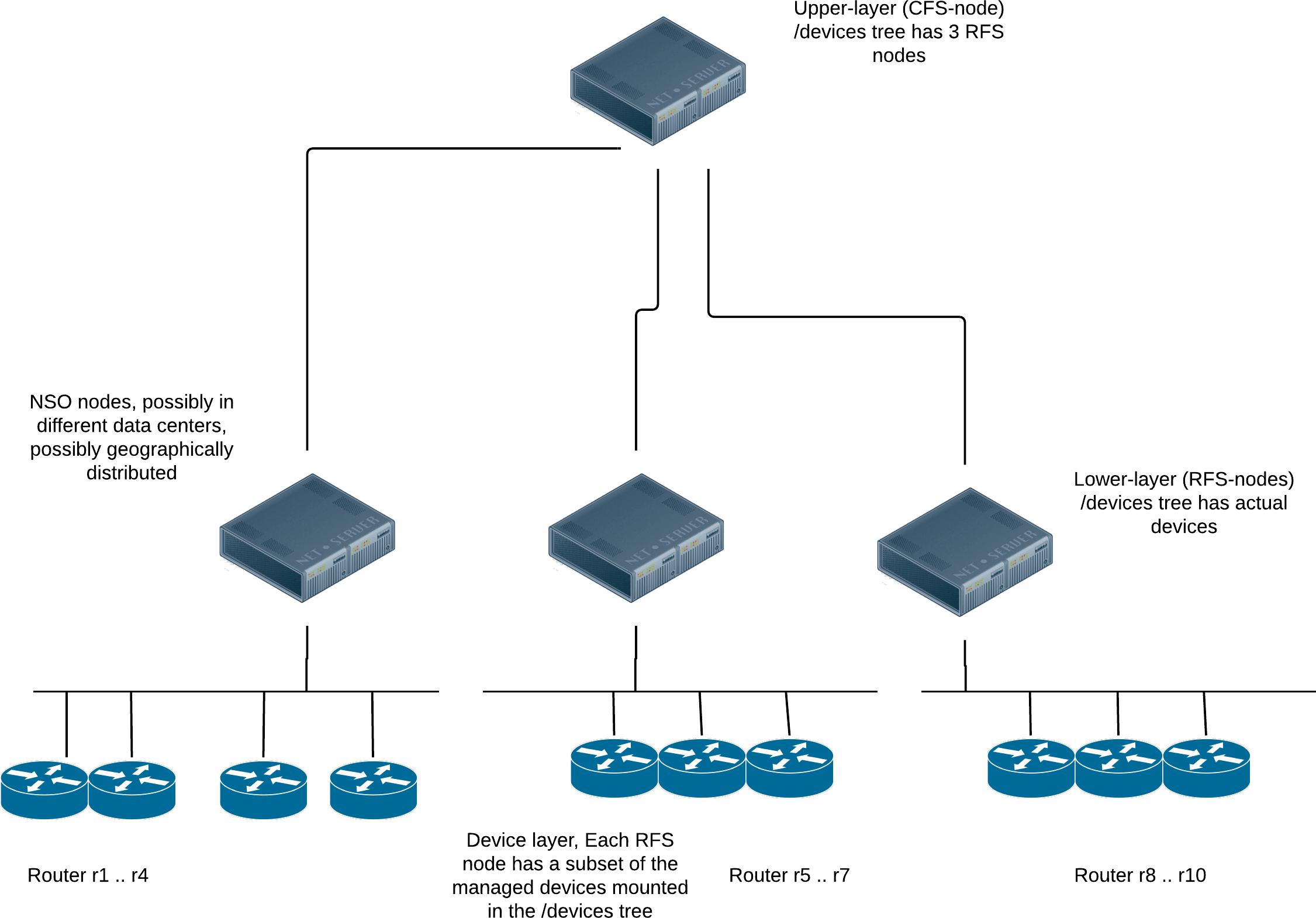
The CFS code (upper-layer) runs in one (or several) NSO cfs-nodes, and the
RFS code (lower-layer) runs in one of many NSO rfs-nodes.
The rfs-nodes have each a portion of the managed devices mounted
in their /devices tree and the cfs-node(s) have
the NSO rfs-nodes mounted in their /devices tree.
The main advantage of this architecture is that we can add arbitrarily many device nodes. The major problems with monolithic NSO applications are memory and provisioning throughput constraints. Especially the device configurations can sometimes become very large. This architecture attempts to address both of these problems as will be shown in the sections below.
Depending on the situation, the separation can be done in different ways. We have at least the following three different scenarios: new green field design, existing stacked services and existing monolithic design.
If you are starting the service design from scratch, it's obviously ideal. In this case you can choose the partitioning at leisure. The CFS must obviously contain YANG definitions for everything the customer, or an order capture system north of the service node can enter and order. However, the RFS YANG models can be designed differently. They are now system internal data models, and you as a designer are free to design them in such a way so that it makes the provisioning code as easy as possible.
We have two variants on this design, one where one CFS node is used to provision different kinds of services, and one where we also split up the CFS node into multiple nodes, for example one CFS node per service type. This latter design caters for even larger systems that can grow horizontally also at the top level of the system.
A VPN application for example could be designed to have two CFS YANG models. One for the infra-structure and then one for a CPE site. The customer buys the infra-structure, and then buys additional CPE sites (legs on the VPN). We can then design the RFS models at will, maybe divide the results of an instantiated cpe-site into 3 separate RFS models, maybe depending on input parameters to the CFS, or some other configuration the CFS code can choose to instantiate a physical CPE or a virtual CPE, i.e., the CFS code chooses where to instantiate which RFSs.
A common use case is when a single node NSO installation grows and we're faced with performance problems due to growth and size. It is possible to split up a monolithic application into an upper-layer and lower-layer service, and we show how to do that in the following chapters. However, the decision to do that should always be accompanied by a thorough analysis determining what makes the system too slow. Sometimes, it's just something trivial, like a bad "must" expression in service YANG code or something similar. Fixing that is clearly easier than re-architecting the application.
Existing monolithic application that are written using the stacked services design can sometimes be easy to rewrite in the LSA fashion. The division of a service into an upper and lower layer is already done, where the stacked services make ideal candidates for lower layer (RFS) services.
Regardless of whether we have a green field design, or if we are extending an existing monolithic application, we always face the same problem of dispatching the RFS instantiation to the correct lower-layer NSO node.
Imagine a VPN application where the customer orders yet another
leg in the VPN. This will (at least) result in one additional
managed device, the CPE. That CPE resides in the
/devices/device tree on one, and only one
of the RFS-nodes. The CFS-node must thus:
-
Figure out which RFS-node is responsible for that CPE.
-
Dispatch the RFS instantiation to that particular RFS-node.
Techniques to facilitate this dispatch are:
-
This first and most straightforward solution to the dispatch problem is to maintain a mapping list at the CFS-node(s). That list will contain 2-tuples that map device name to RFS-node. One downside to this is clearly the fact that the list must be maintained. Whenever the
/devices/deviceis manipulated at one RFS-node, the mapping list at the CFS-node must also updated.It is straightforward to automate the maintenance of the list though, either through NETCONF notifications whenever
/devices/deviceis manipulated, or, alternatively, by explicitly asking the CFS-node to query the RFS-nodes for its list of devices. -
Another scenario is when the RFS-nodes are geographically separated, different countries, different data centers. If the CFS service instance contains a parameter indicating which country/data center is to be used, the dispatching of the RFS can be inferred or calculated at the CFS layer. This way, no mapping needs to be maintained at all.
This architecture scales horizontally at the RFS-node layer. Each RFS-node
needs to host the RFSs that touch the devices it has in its
/devices/device tree.
If one RFS node starts to become overloaded, it's easy to start an additional RFS node for e.g., that geographical region, or that data center, thus catering for horizontal scalability at the level of number of managed devices, and number of RFS instances.
As stated above, the main disadvantages to a monolithic application design are memory consumption and overall throughput. Memory is cheap, so unless the throughput is the major concern, we generally recommend staying with the monolithic application design. However, an LSA design can greatly improve overall throughput, especially in combination with the commit queue. In general we recommend to enable the commit queue in LSA applications. If the commit queue is not enabled, overall throughput is still limited by the slowest device on the network, at least for applications that do not use reactive FastMap.
Let's go though the execution scenario for a set of LSA configurations. The first is the default, no commit queue, and also a standard FastMap application with no Reactive FastMap at all. This is common for many VPN type of applications with NSO. A prerequisite for the discussion below is for the reader to understand the operational behavior of the commit queues as well as the difference between a regular FastMap application and a Reactive FastMap application.
-
A transaction arrives at the CFS node from the northbound, maybe from a customer order portal.
-
The CFS code determines which RFSs need to be instantiated where, NSO will send the appropriate NETCONF edit-config RPCs to the RFS nodes. These are synchronous.
-
The chosen RFS nodes get the edit-config RPCs. The RFS FastMap code runs at the RFS nodes, manipulating the
/devices/devicetree, i.e., updating the managed devices. -
The configuration change is accepted by the choosen devices, and the RFS-node transactions return, thereby replying to the CFS-node, synchronously.
-
The reply to the initial northbound request from the customer portal is sent by the CFS node.
The entire sequence is serialized though the system as a whole. This means that if another northbound request arrives at the CFS node while the first request is being processed, the second request is synchronously queued at the CFS node, waiting for the currently running transaction to either succeed or fail.
If we enable the commit queue between the CFS node and the RFS nodes, we may achieve some increased parallelism in the system, and thus higher overall system throughput. Not much though; here is the execution sequence with commit queue enabled between CFS-node and RFS-nodes
-
A transaction arrives at the CFS node from the northbound, maybe from a customer order portal.
-
The CFS code determines which RFSs need to be instantiated where, NSO will send the appropriate NETCONF edit-config RPCs to the RFS nodes, the transaction is finished. Depending on commit flags (as requested by the northbound caller), a reply is either sent now, or the reply is delayed until all items in the commit queue generated by this transaction are finished.
-
A second request arrives from the northbound, while the first one is being processed by the commit queue. The CFS code determines which RFSs need to be instantiated where. The "where" in the sentence above, means "which RFS nodes" need to be touched. If the set of chosen RFS nodes is completely disjoint from the set of RFS nodes chosen for the first transaction, the second one gets to execute in parallel, if not, it gets queued. Thus just enabling the commit queue between the CFS node and the RFS nodes doesn't buy us a lot of parallelism.
What is required to achieve really high transaction throughput, is to not allow the slowest device to lock up the system. This can be achieved in two radically different ways. Either enable the commit queue between the RFS-nodes and their managed devices, or alternatively, if the RFS FastMap code is reactive, we almost get the same behavior, but not quite. We'll walk through both scenarios. First, enable the commit queue everywhere, we get:
-
A transaction arrives at the CFS node from the northbound, maybe from a customer order portal.
-
The CFS FastMap code determines which RFSs need to be instantiated where, NSO will send the appropriate NETCONF edit-config RPCs to the RFS nodes, the transaction is finished, no need to wait for the RFS nodes to reply.
-
The RFS nodes receive the
edit-configRPC, and the FastMap code is invoked. The RFS FastMap code determines which devices need to be configured with what data, the proposed router configs are sent to the commit queue and the transaction is finished.
Regardless of when additional data is received from the northbound of the CFS node, data is processed and the level of concurrency in a system configured this way is very high.
If the RFS nodes FastMap code is reactive, we get similar behavior since
usually Reactive FastMap applications are very fast during its first
round of execution. Usually something must be allocated, an IP address or
something, thus when the RFS node receives the
edit-config
from the CFS node and the RFS node FastMap code is invoked, that first
round of Reactive FastMap execution returns fast, without waiting for any
provisioning of any actual devices, thus the CFS node
edit-config
executes fast. We will not achieve equally high provisioning numbers as
with the commit queue though, since eventually when devices actually has
to modified, execution is serialized.
It's possible to scale the CFS layer horizontally as well.
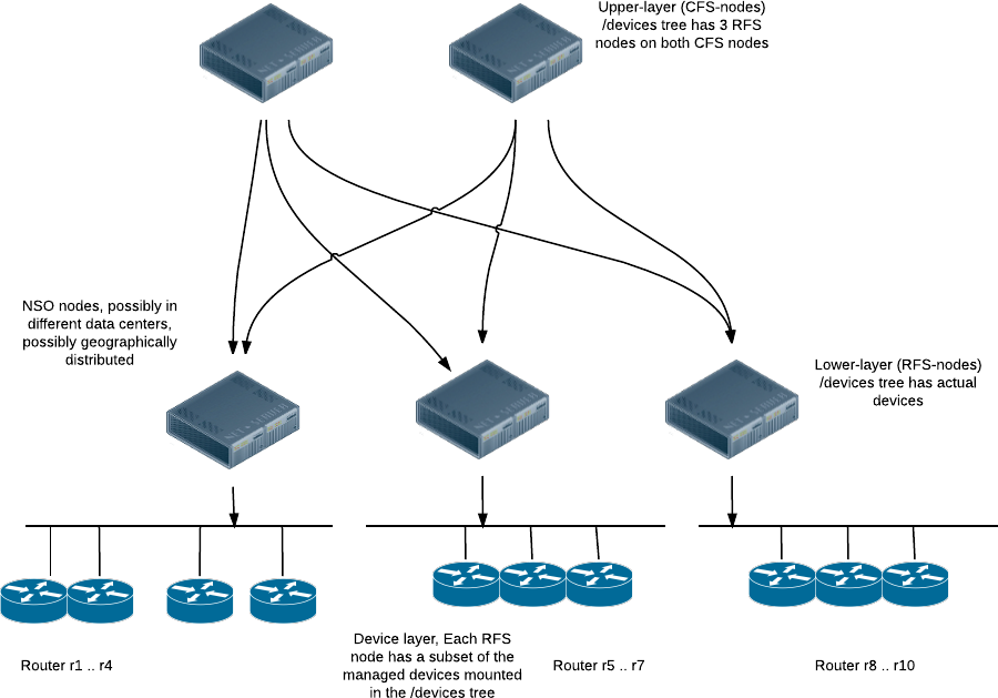
Typically we would assign a separate CFS node per application, or group of applications. Maybe a provider sells L2 and L3 VPNs. One CFS node could be running the CFS provisioning code for L2 VPNs and another CFS node the L3 VPNs.
The RFS nodes though would all have to run the RFS code for all services. Typically the set of service YANG modules related to L2 VPNs would be completely disjoint from the set of services YANG modules related to L3 VPNs. Thus we do not have any issues with multiple managers (CFS nodes). The CFS node for L2 service would see and manipulate the RFSs for L2 RFS code and vice versa for the L3 code. Since there is no overlap between what the two (or more) CFS nodes touch on the RFS nodes, we do not have a sync problem. We must however turn off the sync check between the CFS nodes and the RFS nodes since the sync check is based on CDB transaction ids. The following execution scenario explains this:
- CFS node for L2 VPNs execute a transaction towards RFS node R1.
- CFS node for L3 VPNs execute a transaction towards RFS node R1.
- CFS node for L2 VPNs is now out of sync, the other CFS node touched entirely different data, but that still doesn't matter since the CDB transaction counter has been changed.
If there is overlapping configuration between two CFS applications, the code has to run on the same CFS node and it's not allowed to have multiple northbound configuration system manipulate exactly the same data. In practice this not a problem though.
Clearly the major advantages of this architecture are related to scalability. The solution scales horizontally, both at the upper and the lower layer, thus catering for truly massive deployments.
Another advantage not previously mentioned in this chapter is upgradability. It's possible to upgrade the RFS nodes one at a time. Also, and more importantly is that if the YANG upgrade rules are followed, the CFS node and the RFS nodes can have different release cycles. If a bug is found or a feature is missing in the RFS nodes, that can be fixed independent of the CFS node. Furthermore, if the architecture with multiple CFS nodes is used, the different CFS nodes are probably programmed by separate teams, and the CFS nodes can be upgraded independently of each other.
Compared to a provisioning system where we run everything on a single monolithic NSO system, we get increased complexity. This is expected.
Dividing a provisioning application into upper and lower layer services also increase the complexity of the application itself. Also, in order to follow the execution of a reactive FastMap RFS, typically additional NETCONF notification code has to be written. These notifications have to be sent from the RFS nodes, and received and processed by the CFS code. If something goes wrong at the device layer, this information has to be conveyed all the way to the top level of the system.
We do not get a "single pane of glass" view of all managed interfaces on any one node. Managed devices are spread out over independent RFS nodes.