This documentation corresponds to an older version of the product, is no longer updated, and may contain outdated information.
Please access the latest versions from https://cisco-tailf.gitbook.io/nso-docs and update your bookmarks. OK
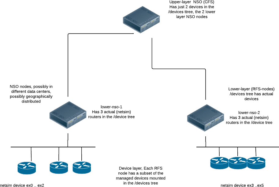
This section describes a small LSA application, which exists as
a running example in the
examples.ncs/getting-started/developing-with-ncs/22-layered-service-architecture
directory.
The application is a slight variation on the
examples.ncs/getting-started/developing-with-ncs/4-rfs-service
example where the YANG code has been split up into an upper-layer
and a lower-layer implementation. The example topology (based on
netsim for the managed devices, and NSO for the upper/lower
layer NSO instances) looks like the following:
The upper layer of the YANG service data for this example looks like the following:
module cfs-vlan {
  ...
  list cfs-vlan {
    key name;
    leaf name {
      type string;
    }

    uses ncs:service-data;
    ncs:servicepoint cfs-vlan;

    leaf a-router {
      type leafref {
        path "/dispatch-map/router";
      }
      mandatory true;
    }
    leaf z-router {
      type leafref {
        path "/dispatch-map/router";
      }
      mandatory true;
    }
    leaf iface {
      type string;
      mandatory true;
    }
    leaf unit {
      type int32;
      mandatory true;
    }
    leaf vid {
      type uint16;
      mandatory true;
    }
  }
}
Instantiating one CFS we have:
admin@upper-nso% show cfs-vlan
cfs-vlan v1 {
    a-router ex0;
    z-router ex5;
    iface    eth3;
    unit     3;
    vid      77;
}
The provisioning code for this CFS has to make a decision on where to
instantiate what. In this example the "what" is trivial, it's the
accompanying RFS, whereas the "where" is more involved.
The two underlying RFS nodes, each manage 3 netsim routers, thus
given the input, the CFS code must be able to determine which RFS node
to choose. In this example we have chosen to have an explicit map,
thus on the upper-nso we also have:
admin@upper-nso% show dispatch-map
dispatch-map ex0 {
    rfs-node lower-nso-1;
}
dispatch-map ex1 {
    rfs-node lower-nso-1;
}
dispatch-map ex2 {
    rfs-node lower-nso-1;
}
dispatch-map ex3 {
    rfs-node lower-nso-2;
}
dispatch-map ex4 {
    rfs-node lower-nso-2;
}
dispatch-map ex5 {
    rfs-node lower-nso-2;
}
So, we have template CFS code which does the dispatching to the right RFS node.
<config-template xmlns="http://tail-f.com/ns/config/1.0"
                 servicepoint="cfs-vlan">
  <devices xmlns="http://tail-f.com/ns/ncs">
    <!-- Do this for the two leafs a-router and z-router -->
    <?foreach {a-router|z-router}?>
    <device>
      <!--
      Pick up the name of the rfs-node from the dispatch-map
      and do not change the current context thus the string()
      -->
      <name>{string(deref(current())/../rfs-node)}</name>
      <config>
        <vlan xmlns="http://com/example/rfsvlan">
          <!-- We do not want to change the current context here either -->
          <name>{string(/name)}</name>
          <!-- current() is still a-router or z-router -->
          <router>{current()}</router>
          <iface>{/iface}</iface>
          <unit>{/unit}</unit>
          <vid>{/vid}</vid>
          <description>Interface owned by CFS: {/name}</description>
        </vlan>
      </config>
    </device>
    <?end?>
  </devices>
</config-template>
This technique for dispatching is simple and easy to understand. The dispatching might be more complex, it might even be determined at execution time dependent on CPU load. It might be (as in this example) inferred from input parameters or it might be computed.
The result of the template-based service is to instantiate the RFS, at the RFS nodes.
First lets have a look at what happened in the upper-nso. Look at the modifications but ignore the fact that this is an LSA service:
admin@upper-nso% request cfs-vlan v1 get-modifications no-lsa
cli {
    local-node {
        data  devices {
                   device lower-nso-1 {
                       config {
              +            rfs-vlan:vlan v1 {
              +                router ex0;
              +                iface eth3;
              +                unit 3;
              +                vid 77;
              +                description "Interface owned by CFS: v1";
              +            }
                       }
                   }
                   device lower-nso-2 {
                       config {
              +            rfs-vlan:vlan v1 {
              +                router ex5;
              +                iface eth3;
              +                unit 3;
              +                vid 77;
              +                description "Interface owned by CFS: v1";
              +            }
                       }
                   }
               }
    }
}
Just the dispatched data is shown. As ex0 and ex5 reside on different nodes, the service instance data has to be sent to both lower-nso-1 and lower-nso-2.
Now let's see what happened in the lower-nso. Look at the modifications and take into account that these are LSA nodes (this is the default):
admin@upper-nso% request cfs-vlan v1 get-modifications
cli {
  local-node {
    .....
  }
  lsa-service {
    service-id /devices/device[name='lower-nso-1']/config/rfs-vlan:vlan[name='v1']
    data devices {
      device ex0 {
        config {
          r:sys {
            interfaces {
   +          interface eth3 {
   +            enabled;
   +            unit 3 {
   +              enabled;
   +              description "Interface owned by CFS: v1";
   +              vlan-id 77;
   +            }
   +          }
            }
          }
        }
      }
    }
  }
  lsa-service {
    service-id /devices/device[name='lower-nso-2']/config/rfs-vlan:vlan[name='v1']
    data devices {
      device ex5 {
        config {
          r:sys {
            interfaces {
   +          interface eth3 {
   +            enabled;
   +            unit 3 {
   +              enabled;
   +              description "Interface owned by CFS: v1";
   +              vlan-id 77;
   +            }
   +          }
            }
          }
        }
      }
    }
  }
Both the dispatched data and the modification of the remote service are shown. As ex0 and ex5 reside on different nodes, the service modifications of the service rfs-vlan on both lower-nso-1 and lower-nso-2 are shown.
The communication between the NSO nodes is of course NETCONF.
admin@upper-nso% set cfs-vlan v1 a-router ex0 z-router ex5 iface eth3 unit 3 vid 78
[ok][2016-10-20 16:52:45]

[edit]
admin@upper-nso% commit dry-run outformat native
native {
    device {
        name lower-nso-1
        data <rpc xmlns="urn:ietf:params:xml:ns:netconf:base:1.0"
                  message-id="1">
               <edit-config xmlns:nc="urn:ietf:params:xml:ns:netconf:base:1.0">
                 <target>
                   <running/>
                 </target>
                 <test-option>test-then-set</test-option>
                 <error-option>rollback-on-error</error-option>
                 <with-inactive xmlns="http://tail-f.com/ns/netconf/inactive/1.0"/>
                 <config>
                   <vlan xmlns="http://com/example/rfsvlan">
                     <name>v1</name>
                     <vid>78</vid>
                     <private>
                       <re-deploy-counter>-1</re-deploy-counter>
                     </private>
                   </vlan>
                 </config>
               </edit-config>
             </rpc>
    }
               ...........
               ....
The YANG model at the lower layer, also known as the RFS layer, is similar to the CFS, but slightly different:
module rfs-vlan {

  ...

  list vlan {
    key name;
    leaf name {
      tailf:cli-allow-range;
      type string;
    }

    uses ncs:service-data;
    ncs:servicepoint "rfs-vlan";

    leaf router {
      type string;
    }
    leaf iface {
      type string;
      mandatory true;
    }
    leaf unit {
      type int32;
      mandatory true;
    }
    leaf vid {
      type uint16;
      mandatory true;
    }
    leaf description {
      type string;
      mandatory true;
    }
  }
}
The task for the RFS provisioning code here is to actually provision the designated router. If we log into one of the lower layer NSO nodes, we can check the following.
admin@lower-nso-1> show configuration vlan
vlan v1 {
    router      ex0;
    iface       eth3;
    unit        3;
    vid         77;
    description "Interface owned by CFS: v1";
}
[ok][2016-10-20 17:01:08]
admin@lower-nso-1> request vlan v1 get-modifications
cli {
  local-node {
    data  devices {
             device ex0 {
               config {
                 r:sys {
                   interfaces {
    +                interface eth3 {
    +                  enabled;
    +                  unit 3 {
    +                    enabled;
    +                    description "Interface owned by CFS: v1";
    +                    vlan-id 77;
    +                  }
    +                }
                   }
                 }
               }
             }
    }
  }
}
To conclude this section, the final remark here is that to design a good LSA application, the trick is to identify a good layering for the service data models. The upper layer, the CFS layer is what is exposed northbound, and thus requires a model that is as forward-looking as possible since that model is what a system north of NSO integrates to, whereas the lower layer models, the RFS models can be viewed as "internal system models" and they can be more easily changed.
In this section, we'll describe a lightly modified version of the
example in the previous section. The application we describe
here exists as a running example under:
examples.ncs/getting-started/developing-with-ncs/24-layered-service-architecture-scaling
Sometimes it is desirable to be able to easily move devices from one lower LSA node to another. This makes it possible to easily expand or shrink the number of lower LSA nodes. Additionally, it is sometimes desirable to avoid HA-pairs for replication but instead use a common store for all lower LSA devices, such as a distributed database, or a common file system.
The above is possible provided that the LSA application is structured in certain ways.
-
The lower LSA nodes only expose services that manipulate the configuration of a single device. We call these devices RFSs, or dRFS for short.
-
All services are located in a way that makes it easy to extract them, for example in /drfs:dRFS/device
container dRFS { list device { key name; leaf name { type string; } } } -
No RFS takes place on the lower LSA nodes. This avoids the complication with locking and distributed event handling.
-
The LSA nodes need to be set up with the proper NEDs and with auth groups such that a device can be moved without having to install new NEDs or update auth groups.
Provided that the above requirements are met, it is possible to move a device from one lower LSA node by extracting the configuration from the source node and installing it on the target node. This, of course, requires that the source node is still alive, which is normally the case when HA-pairs are used.
An alternative to using HA-pairs for the lower LSA nodes is to extract the device configuration after each modification to the device, and store it in some central storage. This would not be recommended when high throughput is required but may make sense in certain cases.
In the example application, there are two packages on the lower
LSA nodes that provide this functionality. The package
inventory-updater installs a database
subscriber that is invoked every time any device configuration
is modified, both in the preparation phase and in the commit phase
of any such transaction. It extracts the device and dRFS
configuration, including service metadata, during the preparation
phase. If the transaction proceeds to a full commit, the
package is again invoked and the extracted configuration
is stored in a file in the directory
db_store.
The other package is called device-actions.
It provides three actions: extract-device,
install-device, and
delete-device. They are intended to be used by the
upper LSA node when moving a device either from a lower LSA
node, or from db_store.
In the upper LSA node, there is one package for coordinating the
movement, called move-device. It provides
an action for moving a device from one lower LSA node to
another. For example when invoked to move device ex0 from
lower-1 to lower-2 using the action
request move-device move src-nso lower-1 dest-nso lower-2 device-name ex0
it goes through the following steps:
-
A partial lock is acquired on the upper-nso for the path
/devices/device[name=lower-1]/config/dRFS/device[name=ex0]to avoid any changes to the device while the device is in the process of being moved. -
The device and dRFS configuration is extracted in one of two ways:
-
Read the configuration from
lower-1using the actionrequest device-action extract-device name ex0
-
Read the configuration from some central store, in our case the file system in the directory.
db_store.
The configuration will look something like this
devices { device ex0 { address 127.0.0.1; port 12022; ssh { ... /* Refcount: 1 */ /* Backpointer: [ /drfs:dRFS/drfs:device[drfs:name='ex0']/rfs-vlan:vlan[rfs-vlan:name='v1'] ] */ interface eth3 { ... } ... } } dRFS { device ex0 { vlan v1 { private { ... } } } } -
-
Install the configuration on the lower-2 node. This can be done by running the action:
request device-action install-device name ex0 config <cfg>
This will load the configuration and commit using the flags
no-deployandno-networking. -
Delete the device from
lower-1by running the actionrequest device-action delete-device name ex0
-
Update mapping table
dispatch-map ex0 { rfs-node lower-nso-2; } -
Release the partial lock for
/devices/device[name=lower-1]/config/dRFS/device[name=ex0]. -
Re-deploy all services that have touched the device. The services all have back pointers from
/devices/device{lower-1}/config/dRFS/device{ex0}. They arere-deployedusing the flagsno-lsaandno-networking. -
Finally, the action runs
compare-configonlower-1andlower-2.
With this infrastructure in place, it is fairly straightforward to implement actions for re-balancing devices among lower LSA nodes, as well as evacuating all devices from a given lower LSA node. The example contains implementations of those actions as well.
If we do not have the luxury of designing our NSO service application from scratch, but rather are faced with extending/changing an existing, already deployed application into the LSA architecture we can use the techniques described in this section.
Usually, the reasons for rearchitecting an existing application are performance related.
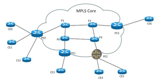
In the NSO example collection, one of the most popular real examples
is the examples.ncs/service-provider/mpls-vpn code.
That example contains an almost "real" VPN provisioning example whereby
VPNS are provisioned in a network of CPEs, PEs and P routers according to
this picture:
The service model in this example, roughly looks like:
   list l3vpn {
      description "Layer3 VPN";

      key name;
      leaf name {
        type string;
      }

      leaf route-distinguisher {
        description "Route distinguisher/target identifier unique for the VPN";
        mandatory true;
        type uint32;
      }

      list endpoint {
        key "id";
        leaf id {
          type string;
        }
        leaf ce-device {
          mandatory true;
          type leafref {
            path "/ncs:devices/ncs:device/ncs:name";
          }
        }

        leaf ce-interface {
          mandatory true;
          type string;
        }

        ....

        leaf as-number {
          tailf:info "CE Router as-number";
          type uint32;
        }
      }
      container qos {
        leaf qos-policy {
           ......
There are several interesting observations on this model code related to the Layered Service Architecture.
-
Each instantiated service has a list of endpoints, CPE routers. These are modeled as a leafref into the /devices tree. This has to be changed if we wish to change this application into an LSA application since the /devices tree at the upper layer doesn't contain the actual managed routers. Instead, the /devices tree contains the lower layer RFS nodes.
-
There is no connectivity/topology information in the service model. Instead, the
mpls-vpnexample has topology information on the side, and that data is used by the provisioning code. That topology information for example contains data on which CE routers are directly connected to which PE router.Remember from the previous section, one of the additional complications of an LSA application is the dispatching part. The dispatching problem fits well into the pattern where we have topology information stored on the side and let the provisioning FASTMAP code use that data to guide the provisioning. One straightforward way would be to augment the topology information with additional data, indicating which RFS node is used to manage a specific managed device.
By far the easiest way to change an existing monolithic NSO application into the LSA architecture, is to keep the service model at the upper layer and lower layer almost identical, only changing things like leafrefs direct into the /devices tree which obviously breaks.
In this example, the topology information is stored in a separate
container share-data and propagated to the
LSA nodes by means of service code.
The example,
examples.ncs/service-provider/mpls-vpn-layered-service-architecture
does exactly this, the upper layer data model in
upper-nso/packages/l3vpn/src/yang/l3vpn.yang
now looks as:
   list l3vpn {
      description "Layer3 VPN";

      key name;
      leaf name {
        type string;
      }

      leaf route-distinguisher {
        description "Route distinguisher/target identifier unique for the VPN";
        mandatory true;
        type uint32;
      }

      list endpoint {
        key "id";
        leaf id {
          type string;
        }
        leaf ce-device {
          mandatory true;
          type string;
        }
        .......
The ce-device leaf is now just a regular string, not
a leafref.
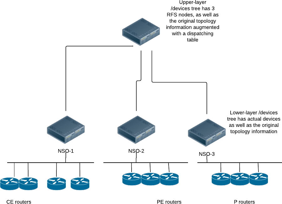
So, instead of an NSO topology that looks like
we want an NSO architecture that looks like:
The task for the upper layer FastMap code is then to instantiate a copy of itself on the right lower layer NSO nodes. The upper layer FastMap code must:
-
Determine which routers, (CE, PE, or P) will be touched by its execution.
-
Look in its dispatch table which lower layer NSO nodes are used to host these routers.
-
Instantiate a copy of itself on those lower layer NSO nodes. One extremely efficient way to do that is to use the
Maapi.copy_tree()method. The code in the example contains code that looks like:public Properties create( .... NavuContainer lowerLayerNSO = .... Maapi maapi = service.context().getMaapi(); int tHandle = service.context().getMaapiHandle(); NavuNode dstVpn = lowerLayerNSO.container("config"). container("l3vpn", "vpn"). list("l3vpn"). sharedCreate(serviceName); ConfPath dst = dstVpn.getConfPath(); ConfPath src = service.getConfPath(); maapi.copy_tree(tHandle, true, src, dst);
Finally, we must make a minor modification to the lower layer (RFS) provisioning code too. Originally, the FastMap code wrote all config for all routers participating in the VPN, now with the LSA partitioning, each lower layer NSO node is only responsible for the portion of the VPN which involves devices that reside in its /devices tree, thus the provisioning code must be changed to ignore devices that do not reside in the /devices tree.
In addition to conceptual changes of splitting into upper- and lower-layer parts, migrating an existing monolithic application to LSA may also impact the models used. In the new design, the upper-layer node contains the (more or less original) CFS model as well as the device compiled RFS model, which it requires for communication with the RFS nodes. In a typical scenario, these are two separate models. So, for example, they must each use a unique namespace.
To illustrate the different YANG files and namespaces used, the
following text describes the process of splitting up an example
monolithic service. Let's assume that the original service resides
in a file, myserv.yang, and looks like the
following:
module myserv {

  namespace "http://example.com/myserv";
  prefix ms;

  .....

  list srv {
    key name;
    leaf name {
      type string;
    }

    uses ncs:service-data;
    ncs:servicepoint vlanspnt;

    leaf router {
       type leafref {
         path "/ncs:devices/ncs:device/ncs:name";
    .....
    }
}
In an LSA setting, we want to keep this module as close to the original as possible. We clearly want to keep the namespace, the prefix and the structure of the YANG identical to the original. This is to not disturb any provisioning systems north of the original NSO. Thus with only minor modifications, we want to run this module at the CFS node, but with non-applicable leafrefs removed, thus at the CFS node we would get:
module myserv {

  namespace "http://example.com/myserv";
  prefix ms;

  .....

  list srv {
    key name;
    leaf name {
      type string;
    }

    uses ncs:service-data;
    ncs:servicepoint vlanspnt;

    leaf router {
       type string;
    .....
    }
}
Now, we want to run almost the same YANG module at the RFS node, however
the namespace must be changed. For the sake of the CFS node, we're
going to NED compile the RFS and NSO doesn't like the same namespace
to occur twice, thus for the RFS node, we would get a YANG module
myserv-rfs.yang that looks like the following:
module myserv-rfs {

  namespace "http://example.com/myserv-rfs";
  prefix ms-rfs;

  .....

  list srv {
    key name;
    leaf name {
      type string;
    }

    uses ncs:service-data;
    ncs:servicepoint vlanspnt;

    leaf router {
       type leafref {
         path "/ncs:devices/ncs:device/ncs:name";
    .....
    }
}
This file can, and should, keep the leafref as is.
The final and last file we get is the compiled NED, that should be loaded in the CFS node. The NED is directly compiled from the RFS model, as an LSA NED.
$ ncs-make-package --lsa-netconf-ned /path/to-rfs-yang myserv-rfs-ned
Thus we end up with 3 distinct packages from the original one.
-
The original, slated for the CFS node, with leafrefs removed.
-
The modified original, slated for the RFS node, with the namespace and the prefix changed.
-
The NED, compiled from the RFS node code, slated for the CFS node.