This documentation corresponds to an older version of the product, is no longer updated, and may contain outdated information.
Please access the latest versions from https://cisco-tailf.gitbook.io/nso-docs and update your bookmarks. OK
Layered Service Architecture (LSA) is a design approach for massively large and scalable NSO applications. Large service providers and enterprises can use it to manage services for millions of users, ranging over several hundred thousand managed devices. Such scale requires special consideration since a single NSO instance no longer suffices and LSA helps you address this challenge.
At some point, scaling up hits the law of diminishing returns. Effectively, adding more resources to the NSO server becomes prohibitively expensive. To further increase the throughput of the whole system, you can share the load across multiple instances, in a scale out fashion.
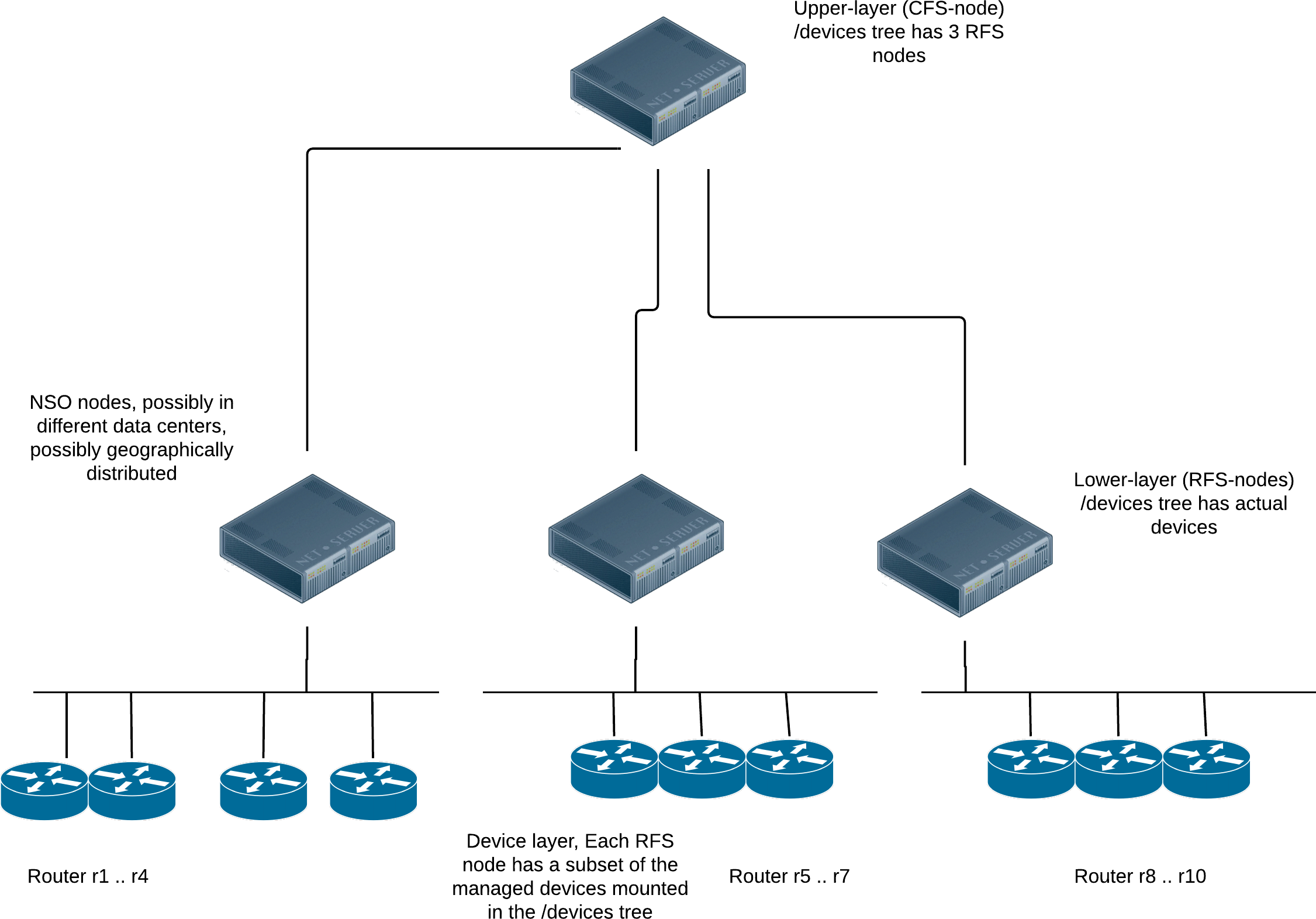
You achieve this by splitting a service into a main, upper-layer part and one or more lower-layer parts. The upper part controls and dispatches work to lower parts. This is the same approach as using a customer-facing service (CFS) and a resource-facing service (RFS). However, here the CFS code (the upper-layer part) runs in a different NSO node than the RFS code (the lower-layer parts). What is more, the lower-layer parts can be spread across multiple NSO nodes.
Each RFS node is responsible for its own set of managed devices,
mounted under its /devices tree, and the upper-layer,
CFS node only concerns itself with the RFS nodes.
So, the CFS node only mounts the RFS nodes under its
/devices tree, not managed devices directly.
The main advantage of this architecture is that you can add many
device RFS nodes that collectively manage a huge number of actual
devices—much more than a single node could.
While it is tempting to design the system in the most scalable way from the start, it comes with a cost. Compared to a single, non-LSA setup, the automation system now becomes distributed across multiple nodes, with all the complexity that entails. For example, in a non-distributed system, the communication between different parts has mostly negligible latency and hardly ever fails. That is certainly not true anymore for distributed systems as we know them today, including LSA.
More practically, taking a service in NSO and deploying a single instance on an LSA system is likely to take longer and have a higher chance of failure compared to a non-LSA system, because additional network communication is involved.
Moreover, multiple NSO nodes present a higher operational complexity and administrative burden. There is no longer a “single pane of glass” view of all the individual devices. That's why you must weigh the benefits of the LSA approach against the scale at which you operate. When LSA starts making sense will depend on the type of devices you manage, the services you have, the geographical distribution of resources, and so on.
A distributed system can push the overall throughput way beyond what a single instance can do. But you will achieve a much better outcome by first focusing on eliminating the bottlenecks in the provisioning code, as discussed in Scaling and Performance Optimization in Development Guide. Only when that proves insufficient, consider deploying LSA.
LSA also addresses memory limitations of NSO when device configurations become very large (individually or all together). If the NSO server is memory constrained and more memory cannot be added, the LSA approach can be a solution.
Another challenge that LSA may help you overcome is scaling organizationally. When many teams share the same NSO instance, it can get hard to separate the different concerns and responsibilities. Teams may also have different cadence or preferences for upgrades, resulting in friction. With LSA, it becomes possible to create a clearer separation. The CFS node and the RFS nodes can have different release cycles (as long as the YANG upgrade rules are followed) and each can be upgraded independently. If a bug is found or a feature is missing in the RFS nodes, it can be fixed without affecting the CFS node, and vice versa.
To summarize, the major advantage of this architecture is scalability. The solution scales horizontally, both at the upper and the lower layer, thus catering for truly massive deployments, but at the expense of the increased complexity.
To take advantage of the scalability potential of LSA, your services must be designed in a layered fashion. Once the automation logic in NSO reaches a certain level of complexity, a stacked service design tends to emerge naturally. Often, you can extend it to LSA with relatively little change. The same is true for brand new, green field designs.
In other situations, you might need to invest some additional effort to split and orchestrate the work across multiple groups of devices. Examples are existing monolithic services or stacked service designs that require all RFSs to access all devices.
If you are designing the service from scratch, you have the most freedom in choosing the partitioning of logic between CFS and RFS. The CFS must contain the YANG definition for the service and its configurable options that are available to the customer, perhaps through an order capture system north of the NSO. On the other hand, the RFS YANG models are internal to the service, that is, they are not used directly by the customer. So, you are free to design them in a way that makes the provisioning code as simple as possible.
As an example, you might have a VLAN provisioning service where the CFS lets users select if the hosts on the VLAN can access the internet. Then you can divide provisioning into, let's say, an RFS service that configures the VLAN and the appropriate IP subnet across the data center switches, and another RFS service that configures the firewall to allow the traffic from the subnet to reach the internet. This design clearly separates the provisioned devices into two groups: firewalls and data center switches. Each group can be managed by a separate lower-layer NSO.
Similar to a brand new design, an existing monolithic application that uses stacked services has already laid the groundwork for LSA-compatible design because of the existing division into two layers (upper and lower).
A possible complication, in this case, is when each existing RFS touches all of the affected devices and that makes it hard to partition devices across multiple lower-layer NSO nodes. For example, if one RFS manages the VLAN interface (the VLAN ID and layer 2 settings) and another RFS manages the IP configuration for this interface, that configuration very likely happens on the same devices. The solution in this situation could be to partition RFS services based on the data center that they operate in, such as one lower-layer NSO node for one data center, another lower-layer NSO for another data center, and so on. If that is not possible, an alternative is to redesign each RFS and split their responsibilities differently.
The most complex, yet common case is when a single node NSO installation grows over time and you are faced with performance problems due to the new size. To leverage the LSA functionality, you must first split the service into upper- and lower-layer parts, which requires a certain amount of effort. That is why the decision to use LSA should always be accompanied by a thorough analysis to determine what makes the system too slow. Sometimes, it is a result of a bad "must" expression in the service YANG code or similar. Fixing that is much easier than re-architecting the application.
Regardless of whether you start with a green field design or extend an existing application, you must tackle the problem of dispatching the RFS instantiation to the correct lower-layer NSO node.
Imagine a VPN application that uses a managed device on each site to securely connect to the private network. In a service provider network, this is usually done by the CPE. When a customer orders connectivity to an additional site (another leg of the VPN), the service needs to configure the site-local device (the CPE). As there will be potentially many such devices, each will be managed by one of the RFS nodes. However, the VPN service is managed centrally, through the CFS, which must:
-
Figure out which RFS node is responsible for the device for the new site (CPE).
-
Dispatch the RFS instantiation to that particular RFS node, making sure the device is properly configured.
NSO provides a mechanism to facilitate the second part, the actual dispatch, but the service logic must somehow select the correct RFS node. If the RFS nodes are geographically separated across different countries or different data centers, the CFS could simply infer or calculate the right RFS node based on service instance parameters, such as the physical location of the new site.
A more flexible alternative is to use dynamic mapping. It can be as
simple as a list of 2-tuples that map a device name to an RFS node,
stored in the CDB. The trade-off is that the list must be maintained.
It is straightforward to automate the maintenance of the list though,
for example through NETCONF notifications whenever
/devices/device on the RFS nodes is manipulated
or by explicitly asking the CFS node to query the RFS nodes for
their list of devices.
Ultimately, the right approach to dispatch will depend on the complexity of your service and operational procedures.
Having designed a layered service with the CFS and RFS parts, the CFS must now communicate with the RFS that resides on a different node. You achieve that by adding the lower-layer (RFS) node as a managed device to the upper-layer (CFS) node. The CFS node must access the RFS data model on the lower-layer node, just like it accesses any other configuration on any managed device. But don't you need a NED to do this? Indeed, you do. That's why the RFS model needs to be specially compiled for the upper-layer node to use as part of a NED and not a standalone service. A model compiled in this way is called device compiled.
Let's then see how the LSA setup affects the whole service provisioning process. Suppose a new request arrives at the CFS node, such as a new service instance being created through RESTCONF by a customer order portal. The CFS runs the service mapping logic as usual; however, instead of configuring the network devices directly, the CFS configures the appropriate RFS nodes with the generated RFS service instance data. This is the dispatch logic in action.
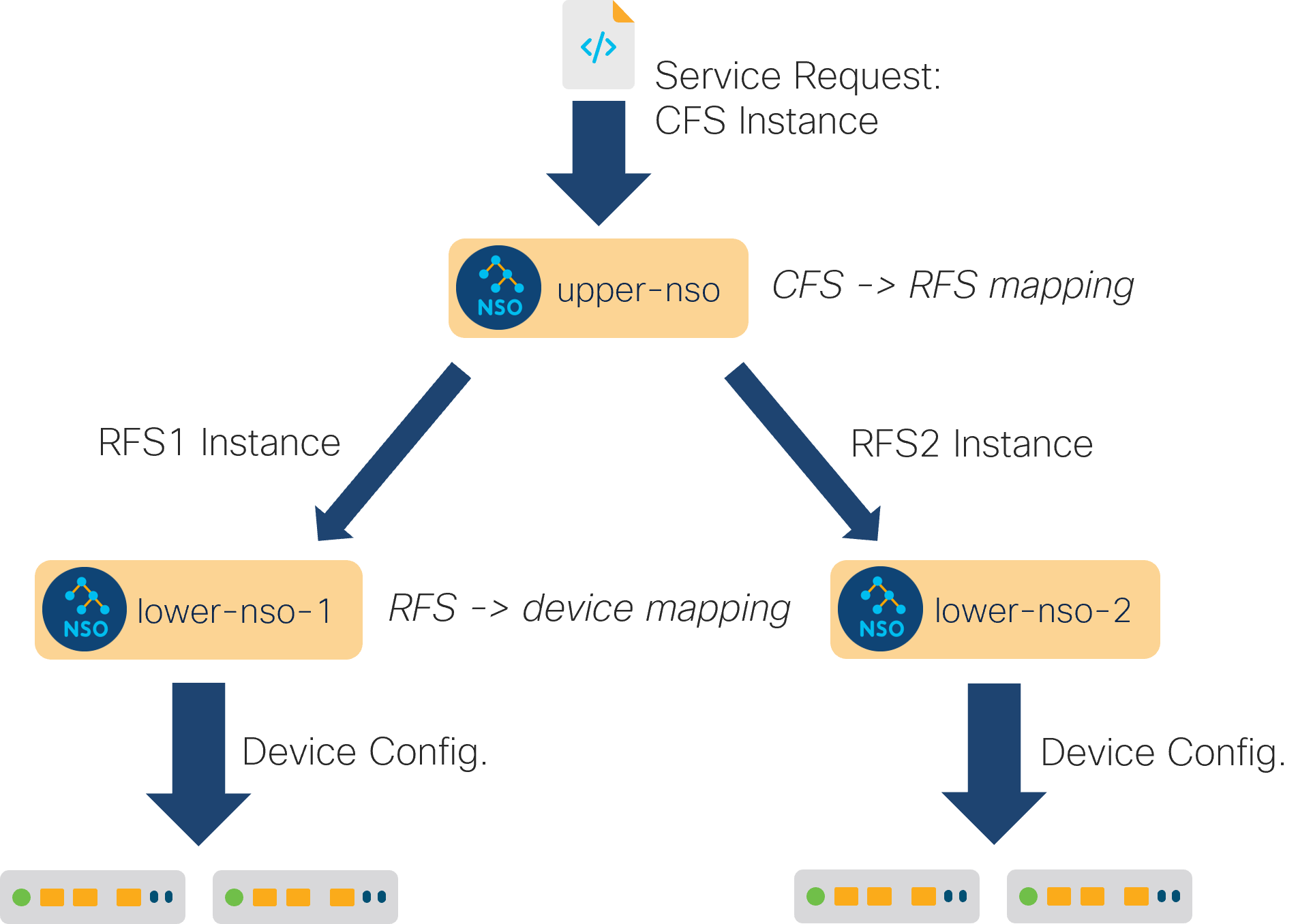
As the configuration for the lower-layer nodes happens under the
/devices/device tree, it is picked up and pushed to the
relevant NSO instances by the NED. The NED sends the appropriate
NETCONF edit-config RPCs, which trigger the RFS FASTMAP code at
the RFS nodes.
The RFS mapping logic constructs the necessary network configuration
for each RFS instance and the RFS nodes update the actual network
devices.
In case the commit queue feature is not being used, this entire sequence is serialized through the system as a whole. It means that if another northbound request arrives at the CFS node while the first request is being processed, the second request is synchronously queued at the CFS node, waiting for the currently running transaction to either succeed or fail.
If the code on the RFS nodes is reactive, it will likely return without much waiting, since the RFM applications are usually very fast during their first round of execution. But that will still have a lower performance than using the commit queue, since the execution is serialized eventually, when modifying devices. To maximize throughput, you also need to enable the commit queue functionality throughout the system.
The main benefit of LSA is that it scales horizontally at the RFS
node layer. If one RFS node starts to become overloaded, it's easy
to bring up an additional one, to share the load. Thus LSA caters
to scalability at the level of the number of managed devices.
But each RFS node needs to host all the RFSs that touch the devices
it manages under its /devices/device tree. There is still
one, and only one, NSO node that directly manages a single
device.
Dividing a provisioning application into upper and lower layer services also increases the complexity of the application itself. For example, to follow the execution of a reactive or nano RFS, typically an additional NETCONF notification code must be written. The notifications have to be sent from the RFS nodes, and received and processed by the CFS code. This way, if something goes wrong at the device layer, the information is relayed all the way to the top level of the system.
Furthermore, it is highly recommended that LSA applications enable the commit queue on all NSO nodes. If the commit queue is not enabled, the slowest device on the network will limit the overall throughput, significantly reducing the benefits of LSA.
Finally, if the two-layer approach proves to be insufficient due to requirements at the CFS node, you can extend it to three layers, with an additional layer of NSO nodes between the CFS and RFS layers.