Module Development Guidelines
Module functionality is only limited to one's imagination subject to available AP power. Applications can include, but are not limited to, RF non-WiFi technologies, environmental monitoring/control, Fog, or compute/cache engines.
Below summarizes key high level module connectivity considerations.
Golden Finger Pin Assignments
The module must implement edge connector fingers (or Golden Fingers Connector) that must mate with a standard right-angle PCIe x4 card edge connector located on the AP3802. The pin assignments for the port are listed here.
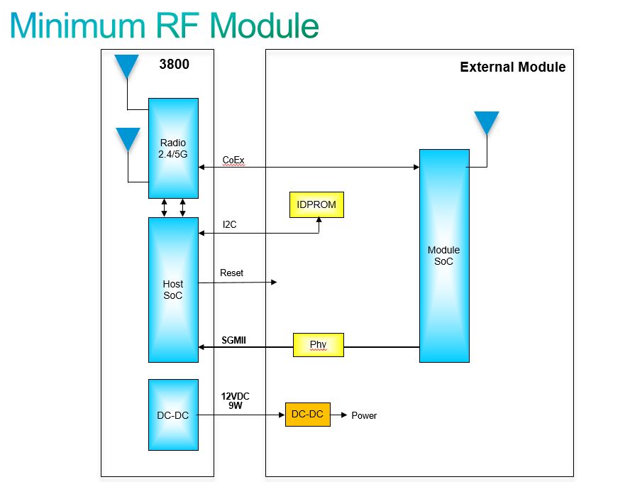
Minimum Module Connectivity
The minimum connection requirements for a module functionality are:
- SGMII host ethernet connectivity
- 12VDC host power
- Host driven reset line
- I2C Serial IDPROM for module identification
- Module presence detection
- Coexistence signaling for 2.4/5GHz radios if relevant
- UART to help diagnose issues with modules. Cisco recommends that third party developed modules have a UART interface for troubleshooting purposes.
Figure 5a: Minimum Module Block Diagram