DSlink Development Documentation
The current state of DSLink development is that any developer exposes their devices, attributes and metric readings in an arbitrary tree of DSA Nodes any form.
This leads to a lack of consistency and adds complexity for solution developers as well as DSLink developer. It is hard to understand, discover and use the exposed data in a systematic manner across many message brokers – especially when more than one DSLink is involved in a solution.
Much unnecessary effort is spend and experience is needed to clean up and transform the data into a useful common structure which is easily useable for dynamic queries.
Rather than every developer proposing their own node structure and every solution developer having to think through the complexity of many use cases, even the potential future protocols not in use, we are proposing an object model that allow for a DSLink to expose device, their attributes as well as metrics in a standard manner.
By providing a standard structure, we enable:
- Faster development of solutions
- Generation of new tools that discover and consume telemetry data without great efforts
- The automatic discovery of devices/assets – for example by the central EFM Asset Registry Database – even if they have been moved around.
- A significant effort reduction for the adaption of software solutions in the case that a new device driver DSLink should be added to a solution
Introduction
The following section explains which problems the object model structure described in this document tries to solve.
Consumer unfriendly DSA Data Models
The DSA protocol is very flexible - basically it defines only "DSA nodes" that are organized in a tree structure below the DSLink´s own "DSA root Node". DSA Nodes can have attributes and configuration items. DSA Nodes can also have actions (which are basically sub-nodes).
This flexibility can introduce a lot of ambiguity how a certain set of real world data providers should be modeled inside the DSA Node structure.
Assuming a DSLink is responsible to expose the information of 50 combined temperature and humidity monitoring devices. The data source for this is a REST server that is exposing all 50 readings as a simple json array of 50 numeric readings.
Without further guidance an overloaded DSLink developers will expose that data in DSA in the "straight forward" approach of creating one DSA node "server" that has a String value (with json syntax) of "[10.3,12.4,12.3,……]".
This "straight forward" approach has many drawbacks:
- Consumer DSLinks (or the UI) which are interested in any of those readings will always have to subscribe to this DSA nodes.
- Consumers will need to parse/consume all 50 temperature readings (and ignore 49 of them if they are only interested in 1 reading) - the responsibility to detect which of the 50 readings has changed between the updates is moved to the consumer of the data.
- There are no individual update timestamps for individual temperature readings
- A lot of data will be moved through the broker network and create unnecessary load (somebody who is interested in 1 temperature reading 3 broker hops away will trigger a flow of 50 data points for each update of a single temperature sensor.
Missing central asset database / Classification Unfriendly DSA Data Models
DSA Broker networks are decentralized. While an individual DSLink may know what kind of real world data it exposes there is no DSA network wide database/authority which is able to answer questions that need data from multiple DSLinks or even brokers.
The Kinetic EFM stack consists of many different modules - one of those modules is the EFM Asset Registry which tries to solve this central Asset Database problem.
To be able to have such a central asset registry database device entries have to be added to this database in a semi or even fully automated way as soon as they appear somewhere inside the DSA Broker network. The DSA node structure which is exposed by a Protocol DSLink needs to guaranty that this "declarative type based discovery" is possible.
This document defines a simple hierarchical object model (object types are "Sensor/Thing", "Channel" and "Observed Property") and mandatory DSA configuration properties for each of those object types.
This object structure enables DSA DQL based automatic discovery of those device assets once they are visible inside the DSA network.
Unit of Measurements ambiguity of DSA Metric Nodes
DSA Metric Nodes provide a standard how to represent the actual numeric or textual value that the metric node represents - however DSA does not provide a standard how to tell the consumer in which unit of measurement (degree Fahrenheit or degree Celsius for instance) this numeric value should be interpreted.
This document defines how to specify the unit of measurement of individual metric/value nodes.
Scope - for which DSLinks is this Standard Document relevant?
The content of this document is applicable for DSLinks which have the role of a Device Driver for the Kinetic EFM Asset Registry.
A Device Driver DSLink is a DSLink which fetches telemetry and structural data from an external sensor system and makes that data available inside the DSA network in the form of DSA Nodes, DSA Configuration Items, DSA Attributes and DSA Values.
All device driver DSLink which wants to expose sensors/devices that can be detected by and use inside the Kinetic EFM Asset Registry need to adhere to this standards.
Here are some examples of those DSLinks:
- DSLinks which fetch sensor telemetry data from individual real world sensors (for example via a proprietary TCP protocol or via MQTT, REST, CoAP, OPC, etc.)
- DSLinks which fetch sensor telemetry data for a set of real world or virtual sensors from external (cloud or on premise) servers (for example a public or private weather station aggregation server like open-weather-map).
Figure 1: DSLinks in scope of this Standard Document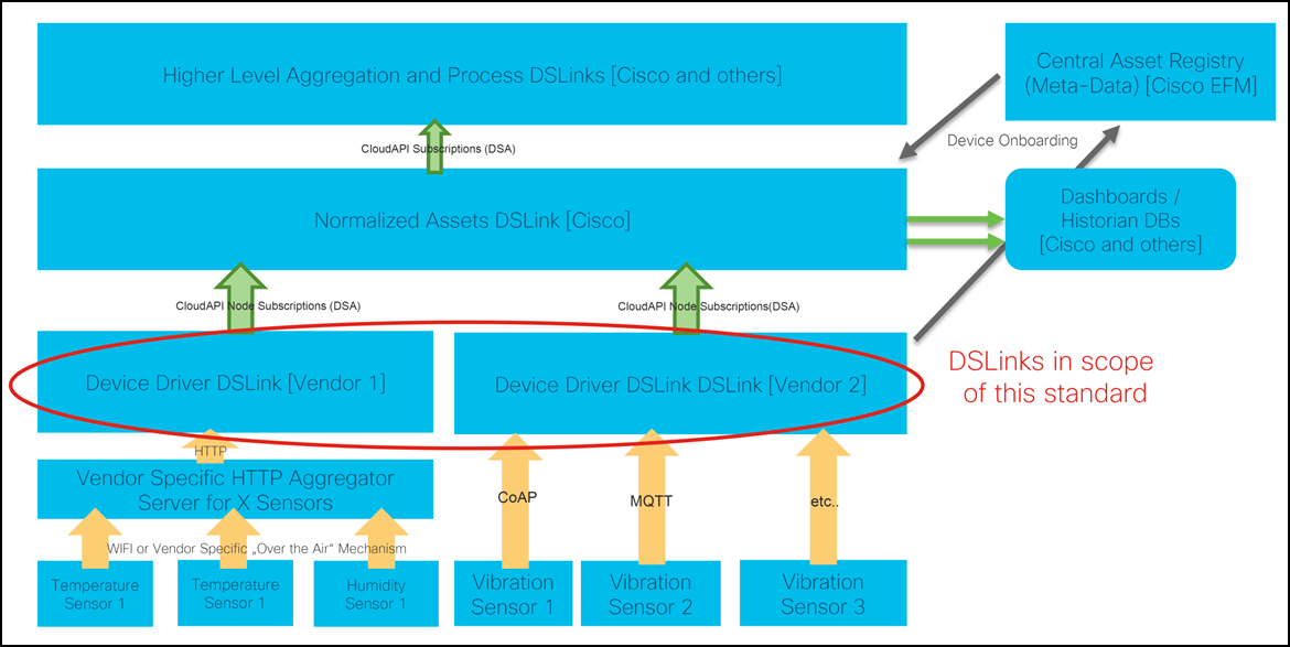
Adhering to the proposed structure in this document is RECOMMENDED but not strictly mandatory for you if:
- The Sensors/Devices which a DSLink exposes are not managed by the EFM Asset Registry (this is most likely valid for early DSLink prototypes only – those which will be deployed in a pure DSA single-broker environment that is not connected to the Kinetic GMM/DCM cloud or to a bigger Multi-Broker EFM installation)
- A DSLink is not exposing devices into the DSA world.
An example of such a DSLink would be a Link which is responsible to monitor other DSA Nodes and to publish alerts into a Cisco-Spark Channel if it detects something unusual. However, authors of such DSLinks may be interested in the structure which is described here because the will most likely need to consume DSA data coming to their DSLink in this structure.
Involved Software Components
Interaction Diagram
Figure 2: Interaction Diagram of Asset Registry, Normalization DSLinks and vendor specific Device Driver DSLinks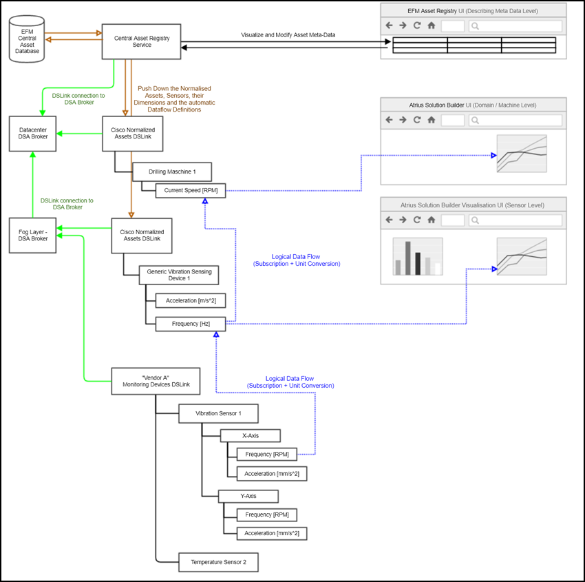
The Asset Registry Service + Database
The EFM Asset Registry is a software component which will be introduced with Kinetic EFM 1.5 into the Edge and Fog Module. It is a central database of known assets across all (interconnected) DSA brokers of an EFM installation. The assets inside the asset registry have a strict data schema which is specific for each asset type and therefore provides a well-organized logical view of all the sensor assets inside a DSA Broker Network.
The asset registry exposes this central database through its own web interface. Inside this user interface end users and administrators are able to see a list of all device/sensor assets - no matter on which DSA broker their managing DSLink exist.
The Device Node Discovery Process
The device node discovery process runs as a background process inside the Asset Registry. The discovery process is responsible to detect new appearances of DSA nodes which represent a physical device.
To make this possible the EFM team has defined a few declarative DSA properties which your protocol DSLink has to maintain inside DSA nodes that represent an onboarding capable device (in most cases a physical or logical sensor device).
The actual DQL query which will be used to find the occurrences of a certain sensor type is part of the device-type specific onboarding definition inside EFM. Here is a potential example of such a DQL search query:
list * | filter ($sysDeviceType="SensorsVendorA-Vibration3Axes-US-v1")
It is important that DSA nodes that represent a device which should be detectable/discoverable by the asset registry have declarative properties that can be used in such a DQL query.
The EFM Normalized Assets DSLink
This Cisco developed component exposes a DSA interface that is being used by the Asset registry to publish the list of normalized assets and their dimensions into the DSA world.
The Normalized Assets DSLink is therefore the aggregation point where device data from multiple Device Driver DSLinks can be consumed by other DSA Subscribers in a convenient flat way.
The intention of this DSLink is that most data consumers (no matter if they are interested in fast changing telemetry data or in slow changing structural dimensions) will subscribe to the DSA Children of the Normalized Assets DSLink and not directly to the Device Driver DSLinks child nodes.
Modifications or Schema changes between different versions of the Device Driver DSLinks can be compensated by this DSLink through different automatic metric flow definition
EFM Device Object Model inside DSA
Summary
This device object model is relevant for the DSA Nodes that your Device Driver DSLink exposes.
The object model which is described in detail below consists of three different object types.
- Device Objects - represent a physical or logical device that should be onboard-able into the EFM asset registry (e.g. a Wi-Fi-connected vibration sensor)
- (Sensor-) Channel Objects - represent a logical or physical grouping section inside the device object (e.g. "X-Axis", "Y-Axis" or "Sensor Health")
- Observed properties - Represents the last known state of an individual telemetry reading (e.g. "acceleration" or "movement frequency" or "battery voltage")
Inside the DSA world all of those 3 object types are all being represented as DSA Nodes - however, the DSA configuration items and the DSA attributes for each of the 3 object types are different and are described in detail tables below.
Those different DSA configuration items are being used by the Asset Registry's discovery and onboarding process to find, interpret and identify the right DSA nodes from your Device Driver DSLink.
The DSA parent/child relationship between Device, Channel and Observed Property Nodes is the same as the ordering in the bullet list above - Observed Properties are being represented inside DSA as child nodes of the channel objects nodes.
Channel objects Nodes are Child Nodes of Device Object nodes and are optional in the model. They may be omitted if a DSLink models a device object that has only 1 sensor channel without any meaningful descriptive attributes (for example a simple 1-channel outside temperature sensor).
In most cases it does not make sense to onboard "devices" that are not exposing any telemetric readings in the form of observed property objects, but in the rare case that you want to make something onboard-able that can only be monitored by a manual process (for instance a 10 year old manual thermometer on the wall) the observable property nodes are also optional.
Device Object Nodes (stuff that should be on-boarded) are mandatory for the EFM Asset Registry in all cases.
The DSA nodes that represent the onboard-able Device Objects may have arbitrary DSA nodes as their parent node. - A DSLink SHOULD use that flexibility for any kind of grouping or structuring of its onboard-able devices.
Currently those higher level grouping nodes will be ignored by the EFM device detection and the higher level grouping will not be visible inside the EFM Asset Registry - however this may change later.
Hint: For now the best way to expose a desired device grouping for individual device objects which is useable inside the Asset Registry and the Normalized Assets DSLink is to specify grouping dimensions properties (e.g. "$floorNumber = 3") inside the device nodes.
Overview Graphic:
The following should give you a rough idea how a Device Driver DSLink needs to expose its device and sensor data so that individual sensors can be on boarded into the Asset Registry.
Figure 4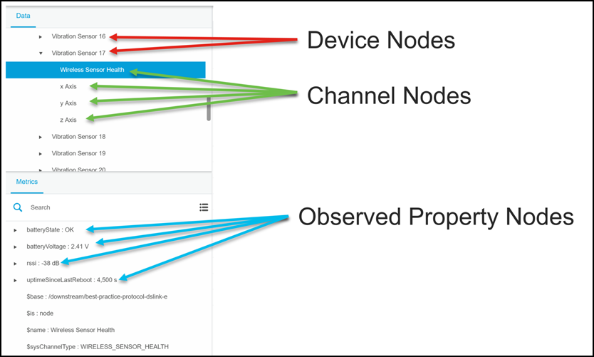
Device Objects
Purpose
DSA nodes which represent an individual onboarding relevant physical or logical device object are being referred to as "DSA Device Nodes".
Device nodes take over the role the digital twin of the real world physical or logical devices that are being monitored by a Device Driver DSLink. They (more accurately their child DSA nodes) represent the last known state of external devices inside DSA.
Device Nodes are the DSA objects which are being onboarded into the EFM Asset Registry. They are the parent nodes for Channel and Observable Property Nodes and are the place where a DSLink writer should expose all the relevant describing information's of a device.
Example of such information: serial number, color, model number, vendor, responsible technical contact etc…
DSA nodes which represent a device
- Represent exactly ONE physical or logical measuring „device" in the real world (see "Sensor") – a Device Node MUST NOT represent a collection of devices (DSLinks need to create multiple instance of a Device Node instead).
- MUST HAVE the DSA configuration item $sysId set (see below)
- MUST HAVE the DSA configuration item $sysDeviceType set (see below)
- Are the DSA parent node for „Channel" DSA Nodes (or directly for „Observable Property" DSA Nodes
- MAY HAVE arbitrary other vendor specific describing (slow changing dimensions) attributes or configurations - as long as they are not within the "sysXXXXXX" namespace)
- SHOULD NOT have a direct DSA $type, ?value or @unit property. - Adding such a property would mixing structural nodes (like this sensor node) with fast changing data nodes (like Observable Property Nodes) – The proposed Data Model separates this into different DSA nodes and the UI is also rendering those nodes at different places.
- SHOULD expose as many describing properties as possible from the device as DSA configurations (serial number, vendor name, firmware version, etc.)
- MAY HAVE vendor specific DSA Actions (blow alarm horn, set sensor scan interval etc...)
Device Object Nodes - Well-Defined DSA properties in Detail
Well defined configuration items
| DSA Attribute- / Configuration Name | DSA Data Type | Constraint | Semantic and Example |
|---|---|---|---|
| $sysDeviceType | string | MANDATORY | Structure and sematic Identifier for the exposed DSA attributes of this node as well as all of its DSA child nodes. Examples: 9947f3dc-3218-4592-9eec-c0433529b889 (This the GUID for a Simulated 3 Axis Vibration Sensor from one of Cisco's Test DSLinks - please do not use this 1:1 in your DSLink - create your own ones for your own exposed node structure. For example: https://www.guidgenerator.com/online-guid-generator.aspx If you change the structure of your DSA Nodes for a particular device you need to generate a new GUID (see "semantic" section below for more details) |
| $sysId | string | MANDATORY | The natural primary key (serial number, MAC address, URL, etc.) of this physical or logical device in the real world. DSA nodes which have the same primary key will be considered to be the SAME entity in the real world (and will therefore not be on boarded multiple times – even if they appear multiple times inside a DSA network at different positions in the DSA nodes tree) Examples: Serial-1237542-xx-1 https://mygateway.cisco.com:443/modbusGW-12/Register-123 4B-36-62-A5-1B-B1 |
$sysDeviceType
Semantic
This DSA configuration item acts as a textual identifier for the exposed DSA sub structure (child nodes and their meaning) of the physical sensor DSA node. It has therefore almost the same role as a Microsoft COM development interface GUID.
The value of this DSA configuration item will be used by the asset registry's device discovery mechanism (inside a DQL query) to find all instances of this particular device type inside the DSA broker network across multiple brokers.
The value will also be used to lookup a collection of Meta data for this Device Type. The Meta data will be maintained in the Asset Onboarding Definition Database inside the Asset Registry. Some of that data (for example a human readable type description of that device and its vendor as well as model-name) will be visible inside DSA as well as inside the Asset Registry's own User Interface.
It is important that two devices node instances that represent identical hardware and software configurations (this includes the identical or structurally compatible software versions of the Device Driver DSLink) have also identical $sysDeviceType values.
Concrete example: If a DSLink exposes 100 instances of a "VendorX Temperature Sensor"- Model A through 100 DSA Device Nodes all of those device nodes MUST HAVE the same $sysDeviceType value.
However:
Due to the fact that the automatic dataflow mapping from your Device Driver DSLink towards the Normalized Assets DSLink is also being defined by the sysDeviceType value it is important that in the case that a new software version of a Device Driver DSLink changes the child structure of a Sensor Node in a way that is incompatible with an existing onboarding definition (examples below) the device type GUID for this particular hardware type HAS TO BE changed by the DSLink developer to a new (random) GUID or a new version of a versioned type string.
Here are some examples for a necessary Device Type GUID change inside the code of your DSLink:
After a DSLink Software Change the x-Axis vibration frequency of a specific 3 axis vibration sensor is no longer exposed at the relative DSA path /xAxis/frequency but instead exposed at /axis-x/frequency.
A GUID change for the same hardware type is also necessary if it is desired (for some other reasons) that existing onboarding definitions do no longer match on device nodes of this particular hardware (one reason could be that there is also an updated onboarding definition and the old one should no longer match) – one of the concrete reasons for that would be that the device vendor name needs to be changed due to a company renaming.
Format and Example
A Global Unique Identifier ( GUID ) ( preferred ) OR a human readable type STRING which fulfills the purpose of a unique interface description (see semantic below)
GUID Example: 9947f3dc-3218-4592-9eec-c0433529b889
(unreleased test version of a 3 axis vibration sensor from a Simulation DSLink developed by Cisco)
If you prefer to use a human readable string instead of a GUID the following format is recommended:
< DSLink-Developer-CompanyName >-< DeviceVendorCompanyName >-< Device Model Number >-< NODE_STRUCTURE_VERSION_NUMBER >
Example:
*Cisco-OpenWeatherMap-GenericStation-V2 *
(this node represents a generic weather station from OpenWeatherMap.org that is being exposed by Version 2 of a DSLink that was developed by Cisco)
This semi-formal structure avoids most possible collisions between different DSLink developers for the same target device and allows for structural changes in later software versions of a DSLink.
$** sysId**
Semantic
The EFM Asset Registry will use this field to detect if the device is already on-boarded into the EFM Asset Registry database.
The combination of $sysDeviceType and $sysId acts as the primary key for assets inside the EFM Asset Registry.
Due to the fact that many Devices will have the same $sysDeviceType value (because they represent the same type of hardware/device) $sysId MUST BE a strong primary key inside the class of all devices from a specific device type.
Due to its primary key nature $sysId of a device MUST NOT change if you deploy a new firmware version on the same physical device or change the exposed node structure (due to a DSLink Update for instance). $sysID should NEVER change for the same physical device instance. – If it changes the same device will be on boarded a second time into the Asset Registry database and you will need to clean up the duplicates manually.
In the case that a DSLink exposes the same physical device multiple times (oneB reason would be that the DSLink exposes two different organizational hierarchy's at the same time) both DSA Nodes MUST HAVE the same $sysId value.
In later EFM versions there will be workflows which allow to detect that the DSA path position of an already on-boarded Device Node has changed (usually due to a broker hierarchy change) – the information which will be used to identify the matching pairs of Device Nodes will be the $sysId property of those Device Nodes.
Format and Example
- The primary key of a device can be an arbitrary DSA string value of reasonable length
- It is ok to use a GUID or a UUID here (but if you can use something human readable like a serial number or something which is printed on the physical sensor itself that is preferred)
- it is ok to use an URL or a Network MAC here
Examples:
"Serial-1237542-xt-1"
"4B-36-62-A5-1B-B1"
"123112311"
"Europe//Germany//Kassel" (Weather Station in Kassel)
(Sensor-)Channel Objects
Purpose
Instances of Channel Objects are digital twins of a logical or functional sub-part of a physical or logical device object. Channel Objects are represented as DSA Nodes and ARE OPTIONAL in the EFM Object Model - if your underlying device does not have any meaningful metric grouping concept at all the "Observed Property" Nodes are the direct DSA child nodes of a the DSA Node that represents the Device Object.
Background: Physical Devices are often separated logically because:
- They support multiple real world Sensor and Actor Channels (i.e. a 4 Outlet power plug may supports 4 real world channels - 1 for each outlet – and on top of that it may support a few device-health channels (UPS Battery Voltage, Wi-Fi-Strength, etc…)
- They monitor many different states and want to group them to make it easier to understand the meaning of a telemetry reading (i.e. Air Quality Metrics and Room Climate Metrics are being monitored by the same physical Device)
- They want to split their state data into real external telemetry readings („read only observations") and internal configuration settings which may be „read/write"
- They provide Meta data for "Device Health" – for example battery voltage of the sensor itself and want to separate that from the real telemetry readings from the outside world.
Channel Nodes as a concept try to allow to mirror such structural groupings inside DSA between a physical (or logical) device node and the actual telemetry value nodes.
Nodes of this type MAY have other describing/dimensional vendor specific properties. They may also contain channel and vendor specific DSA actions (for example: "turn on" / "turn off" / "reset counter" etc.)
To keep the structure simple Channel Nodes SHOULD NOT BE NESTED into each other. Channel Nodes should only act as DSA parent nodes for "Observable Property" Nodes. (See below). This restriction may be removed in later versions – but the concept for nesting of groups is not yet done)
If you are exposing channel nodes for logical sub-sections of your device it will be possible to configure the EFM Asset Registry Sensor Discovery Mechanisms to actually detect and onboard Channels (no matter under which sensor type they are being placed).
This can be helpful if you have a lot of device types that are effectively exposing the same channels but are not exactly the same device type (One use case for that are different country versions of a power consumption sensor - they will most likely all expose a channel "current power demand" with the same structure - but they will have different sensor types because you still want to be able to differentiate different country versions of a device in the onboarding process because they may have different meta data (pictures, design-voltages, etc.)
In that scenario the $sysChannelType property of the Channel DSA Node can be used to identify all the relevant ""CurrentPowerDemand" channels no matter which concrete $sysDeviceType attribute their parent node has.
The following screenshot is a selection of a Channel Node inside the EFM Dataflow Editor.
Figure 4: Selection of the "Sensor Health" Channel Node of a 3 Axis Wireless vibration sensor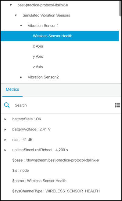
Channel Object Node - Well-Defined DSA properties in Detail
Well defined configuration items
| DSA Attribute- / Configuration Name | DSA Data Type | Constraint | Semantic and Example |
|---|---|---|---|
| $sysChannelType | string | MANDATORY | Structure Identifier for the exposed DSA attributes of this channel node as well as all of its DSA child nodes. Example 1: bcdf7742-b3c5-4d20-b190-a7c8f6e861cc This example uses a GUID to specify the vendor specify structure. Human readable examples: "CURRENT_POWER_CONSUMPTION_1.1""VIBRATION_ON_AXIS_v1" "CURRENT_ROOM_CLIMATE_v2" "DESIRED_ROOM_CLIMATE_v1" |
$sysChannelType
Sematic
The sensor channel type can be used by a data consumer to derive the rough semantic of the node as well as the exact child structure of the channel node.
In combination with the $sysDeviceType attribute of its parent node AND the last part of the DSA path of the channel node (e.g. /outlet3) as well as the vendor specific channel type documentation it can be used by data consumers to derive the exact semantic of the observable property nodes (metrics) of this Sensor Channel Node even if the actual channel name is dynamic.
This allows for example to identify all "current power demand" channels of a multi-plug remote controllable power outlet without the need to know how many concrete plugs this outlet has. A consumer can simply iterate over all channel nodes with a $sysChannelType property of "CURRENT_POWER_DEMAND_V1" that are DSA child nodes of Device Nodes with the $sysDeviceTypes "Cisco-VendorX-PowerMeterY-V2" or "Cisco-VendorX-PowerMeterY-V3"
Two channel instances which have logically (observed property sub nodes) the same structure and roughly the same semantic (for instance: all represent a monitored vibration, but they measure the vibration in different angles (x,y,z-axis) SHOULD have the same channel type - even if they are children of DIFFERENT sensor types (indoor-vibration sensor vs. outdoor capable vibration sensor). The exact semantic of a channel node should be deferrable by the combination of the technical name of the DSA node and the channel type value.
Two channel node instance which do NOT HAVE the same child structure MUST NOT have the same $sysChannelType value. (Otherwise consumers will potentially try to access child properties that do no longer exist).
The values that a DSLink uses inside $sysChannelType should therefore be somehow versioned – or a GUID is being used.
What is semantically identical is a decision of the DSLink-Writer and/or the sensor vendor. There may be scenarios where two channel types expose exactly the same structure but they are in all means not semantically equivalent.
A DSLink writer needs to document the semantic of the $sysChannelType values that he has chosen in some sort of non-formal external documentation that can be distributed with the Device Driver DSLink Package.
Format and Example:
The $sysChannelType configuration can be a reasonable long String human readable string (in that case you should consider to version it so that you can change the structure of your sub-nodes in a new version) or a Standard GUID.
DSLink writer defined channel type values MUST NOT start with "sys". (The sys prefix is reserved for future EFM internal usages like generic "sensor health/reachable"-channels that allow for standardized reachability visualization across Multiple DSLink- and Sensor-Vendors.
Examples:
"WIRELESS_SENSOR_HEALTH_V1.0"
"CURRENT_POWER_CONSUMPTION_V4.1"
"3303915d-e0b0-4067-b9f8-be83f5c3aaec"
"e814f1b1-e60d-49cd-a5e7-1fb0294f76e6"
Observed Property (Metric) Nodes
Purpose
DSA nodes of this node type represent the last known state of the actually monitored telemetry data points. This means Observed Property Nodes have a (potentially fast changing) DSA value - they appear under the "Metrics" Tab inside the Dataflow Editor UI and the EFM Asset Registry's "Normalized Assets DSLink" will subscribe to their DSA value. To save bandwidth from the DSA Brokers to the EFM Asset Registry the actual values of an Observable Property Node will only be available through DSA subscribe mechanisms inside EFM and will NOT BE available inside the EFM Asset Registry in EFM 1.5.
Their current value (DSA "getValue()" or a DSA value subscription) represents the last known value of the observed property (e.g. 1.92) and their "$sysUnitName" property represent the unit in which the value should be interpreted (e.g. "volt").
They may also have a maintained unit symbol (e.g. "V" ) inside the @unit attribute - however this is just for display purposes inside the Dataflow Editor UI – it is important to know that only their $sysUnitName configuration item will be considered by the EFM Normalization DSLink and the automatic unit-conversion logic upstream.
Nodes of this type MAY have other describing vendor specific properties (accuracy, expected range, alarm thresholds etc). Keep in mind that describing properties that belong to the channel or to the physical device (e.g. serial number, responsible admin etc) are better maintained at the channel and device objects of an observed property node.
Figure 5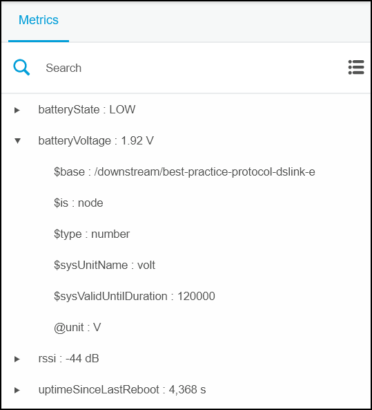
Well defined configuration items
| DSA Attribute- / Configuration Name | DSA Data Type | Constraint | Semantic and Example |
|---|---|---|---|
| DSA Node Name (this is the last part of the nodes DSA path) |
string | MANDATORY (AS PER DSA) |
The semantic and the technical name of the Observed Property (must be unique for the same parent node). This "name" is NOT the DSA Nodes Display name (which unfortunately IS a DSA configuration item named "$name"). This "name" is the last part of the DSA path of this node and needs to be specified during the Node Construction inside the Constructor of the DSA node object. Examples: room_temperature relative_humidity movement_distance movement_acceleration frequency throughput speed |
| $sysValidUntilDuration | integer | OPTIONAL | The duration (in milliseconds) after which this observed value should no longer be considered to be up to date / valid. Example: (represents 1 minute) 60000 |
| $sysUnitName | string | MANDATORY (for numeric values) OR MUST NOT EXIST (for non-numeric values) |
The NAME (and not the SYMBOL) of the Measurement Unit (only for numerical values that have a unit) – has to be a name from the "unitsOfMeasurements" CSV file Examples:"degree Celsius" "degree Fahrenheit" "meter per second squared" "volt ampere" "volt" |
| ?value (this is usually being set via the "setValue()" method in the DSLink SDKs) |
any DSA value type | OPTIONAL (can be null for unknown value) |
the last seen value of this observed property Example: 22 134.12 "OPEN" "CLOSE" |
| $type | string | MANDATORY | The DSA value type of ?value Example: number int string bool map array See org.dsa.iot.dslink.node.value.ValueType |
$sysUnitName
Semantic
$sysUnitName defines the unit of measurement in which the actual node value must be interpreted by consumers. It is therefore MANDATORY for all observable property nodes that have a numeric value.
Observable Property Nodes which represent a textual state (like "OPEN" / "CLOSE" / "CONNECTED" / "UP" / "DOWN" etc.) and not a numeric value MUST NOT HAVE a $sysUnitName configuration item (DSLinks should not create it).
In most cases the consumer of observable property nodes is the EFM Normalized Assets DSLink which will subscribe to the observable property nodes value nodes and perform the necessary unit conversion into the normalized data model. However, also other DSA consumers may subscribe to your observable property nodes and will make use of that information.
The unit of an observed property SHOULD be related to the actual meaning (inside temperature should be in "degree Celsius") however, if that is not possible because the conversion formula is not known at the time of writing the Device Driver DSLink link it is acceptable to report a "temperature" in "volt" or "milliampere" as long as the conversion formula can be found in some other documents. The actual conversion to "degree Celsius" can then be done by the EFM Normalized Assets DSLink in that scenario.
Low Level Device Driver DSLinks do NOT NEED to try to establish a cross-vendor, cross sensor type standard regarding units of measurements (example: all temperature readings have to be in "degree Celsius" and all accelerations have to be in "meter per square second") it is perfectly OK to report temperature in degree Fahrenheit or Kelvin and to report acceleration in millimeter per square second" if that is the appropriate unit with the right precision. However, it obviously does not hurt if a DSLink uses metric units.
The Cisco Kinetic team has compiled an extensive list of unit of measurements from a wide variety of sectors. To be able to perform a reliable conversion into a desired target unit it is absolutely mandatory that your DSLink uses those well-defined units of measurement names for numeric telemetry data.
The list of well-defined units of measurement names is available as a CSV file. The values that are allowed for $sysUnitName are inside the column "system.measurement.uomName" inside that separate file.
Important for dynamic units of measurement in Observed Property Nodes:
In the case that your DSLink has the need to change $sysUnitName for a concrete node AND is sending value updates in the meantime it is likely that for a short period of time the values are interpreted in the old unit of measurement.
Therefore the same physical sensor/channel should not report temperature in "degree Celsius" for a few updates and then switch to "degree Fahrenheit" for the next few updates. Sometimes it may not be avoidable to change the $sysUnitName value during runtime of the DSLink (for example if the user has changed the unit in the external source system) - but in that case it is to be expected that due to asynchronous behavior (it is uncertain if the configuration update will arrive at a consumer before the value update) a few values in the new format are being considered to be from the "old" unit (which may lead to wrong unit conversions until the correct source unit name reaches all receivers)
This can lead to problem that a receiver may end up with a few (milli-)-seconds of wrong converted values above the EFM Normalization DSLink Layer. This may trigger "out of bound" alerts behind the normalization DSLink.
To make this race condition unlikely we suggest that you change $sysUnitName of concrete observations only during the startup of a DSLink (before publishing values) or – if that is not possible – consider to suspend sending value updates for a few seconds from the moment on where you have changed $sysUnitName of a node to be somewhat sure that everybody has received the new unit of measurement before sending value updates again. If even that is not possible consider to use a compound value which holds value and unit of measurement. (But consider the drawbacks of using compound values – see below. Future versions may have a better synchronization mechanism.
Format and Example
The value has to be one of the known units of measurement names in textual representation.
A separate CSV/Excel file with hundreds of units of measurements is part of this standard document distribution.
Figure 6: Extract from the units of measurements list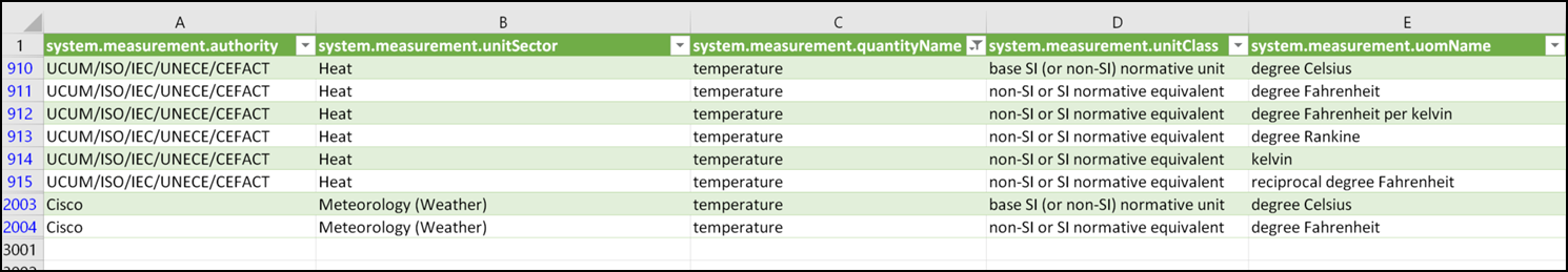
Examples of unit names from that file:
"degree Celsius"
"degree Fahrenheit"
"meter per second squared"
"volt ampere"
"volt"
?value
Semantic
The observed property node represents a real world data point that is being observed by a sensing device. The "?value" property of observed property nodes represent the last known data point of this observed real world data point.
The exact semantic of the value of an observed property node depends on
- the type of parent device ($sysDeviceType) (e.g. "VendorA-PowerConsumptionSensor-Model X1-V1")
- the name of the parent channel (e.g. "outlet01" vs "outlet02")
- the name of the observable property node itself (e.g. "peakConsumptionLast60Minutes" vs "currentPowerDemand")
The value itself holds always a combination of the actual last known state and the timestamp when this state was observed.
In many cases the timestamp of the observation is different from the timestamp that the DSLink is being informed by an external system of the modification. The timestamp of the value of an observable property node SHOULD always be the actual timestamp of the observation and not the timestamp of receiving the information. (See phenomenonTime). The actual timestamp of a DSA value can be specified by a DSLink. In the Java SDK this can be done via the following function: org.dsa.iot.dslink.node.value.Value#setTime(long)
Numeric Source Values:
If your data point is usually being represented as a integer or a floating point number (a temperature, an acceleration, a frequency etc…) but you receive the data it from an external data source in a string representation (for example because your data-source is an XML attributes where everyting is a String value) it is mandatory for a Device DSLink to parse the String value into the appropriate numeric DSA data type.
The "Unknown/Unspecified" Value:
In the case that a sensor is unable to determine the correct last known value state of an observable property it should set the "null" value on the observable property node to inform external subscribers that the value is currently unknown.
Example from the Java SDK:** temperatureReadingNode.setValue(null);
Other SDKs may have a different mechanism to specify the unknown value
Compound Data Types
There is no explicit restriction on the allowed DSA value types for the value field of an observed property - any DSA value type is allowed if it makes sense for the real world item that is being observed – this includes the DSA compound value types "array" and "map".
If you have a combined observation value which are usually being consumed together (or where it is mandatory that a receiver always gets a complete set of values to ensure strong consistency and avoid subscription race conditions) it is acceptable to use a string datatype with JSON content or a DSA map/array datatype.
However – DSLink developers should keep in mind that those compound value types can make it hard to consume only on certain parts of the compound data structure.
It is also more complicated to render time-series of individual metrics inside a UI that are part of a combined/structured DSA value. In most cases a server side dataflow is needed to extract the number which should be visualized over time.
If you are exposing structured observation data (for example a geographical position in the form of a "lat/long/altitude" array, or in the form of a map with 3 entries, a DSLink should consider to expose the individual values as well in separate observed property nodes (preferable below the same channel parent node).
In the GeoJSON example it would for example make sense to make the altitude available as an additional dedicated observed property node. (Latitude and longitude may not make sense individually, unless somebody wants to chart latitude and longitude separately in line-charts over time).
Those additional / duplicate observable property nodes do not create a lot of extra load on a DSA Broker if nobody subscribes to them – but they allows a receiver which is only interested in the "altitude" of a GeoJSON object to subscribe individually on the dedicated "altitude" observed property node without the need to extract that data from a combined GeoJSON.
Example:
String value types
"OPEN"
"CLOSE"
3.1415
1024
true
false
$sysValidUntilDuration
Semantic
While the ?value attribute encompasses a timestamp when a value was first observed in the real world it DOES NOT inform a subscriber for how long he should assume this value should be considered valid.
$sysValidUntilDuration specifies this duration in milliseconds (after the timestamp which is encorporated in the value attribute).
$sysValidUntilDuration is an OPTIONAL configuration item for Observable Property Nodes – if it is not maintained a receiver / subscriber will choose his own expire timestamp based on the phenomenonTimestamp that is part of the value object.
A DSLink may decide to change this value dynamically based on the number of updates it gets from his external data source. An advanced subscriber may use $sysValidUntilDuration to consider a sensor reading "stale" or "outdated" as soon as the current system time is bigger than the phenomenon timestamp of the observed property plus $sysValidUntilDuration. It is in the responsibility of the receiver to decide what it does with that information. Some receivers will ignore such value updates – others will flag the sensor as "offline" or "unreachable".
In the case that the property is maintained by a DSLink it is in the responsibility of the sending DSLink to use a meaningful duration value.
For all sampling DSLinks (DSLinks which poll information every X seconds/minutes from an external REST server for example) the value should be slightly bigger than the sampling interval. This allows upstream subscribers to estimate the freshness of a returned value without the need to know the sample interval of the DSLink.
Example:
A DSLink is fetching temperature data from a wireless temperature sensor which is publishing data every 10 minutes.
The $sysValidUntilDuration for the observable property nodes representing the temperature reading should be around 660000 (11 minutes). After 11 minutes without an update a Visualization Dashboard may indicate that there is a connection issue and the temperature reading is therefore outdated. If the DSLink needs to reduce it´s sample interval to 30 minutes (maybe due to licensing limits) the DSLink should use a bigger valid until duration (31 minutes) and the UI can consider the reading valid for that increased period before rendering an outdated warning.
FAQ
Object Model related questions:
Is there an Example DSLink which implements this Object Model?
Yes an example DSLink implemented in Java which simulates Vibration Sensors is available and is part of this documentation package.
What Kind of Sensor Data should a Device Driver DSLink expose into DSA?
General Guideline: Expose as much detail from the device/sensors as possible into DSA - for instance do not only expose the actual sensed temperature reading of a wireless temperature sensor readings - if you can a DSLink should also expose the sensors own telemetry data and its meta data. Examples of that kind of data:
- Sensor Type
- Device Battery Level (voltage of the build in battery)
- Radio Quality (RSSI) -how good is the communication from the wireless sensor to its wireless access point?
- Device Uptime (when was the Sensing Device last power-cycled?)
- Sensor Firmware Version Number
- Sensor Hardware Revision
- Sensor Serial Number
- Sensor WIFI MAC address
How to expose sensor data from a Device Driver DSLink?
Allow for declarative (IOT DSA DQL pattern matching) finding of Sensors (by their type) and their Capabilities (by their exposed Channel types)
Plan for different access rights on individual real world „observed properties" (and channels) of a sensor
Make the detection and consumption of your data possible by non-human consumer DSLinks (so called Engine DSLinks)
Make vendor specific device, channel and metric semantic detectable and usable
Make vendor specific structure and hierarchies useable (either by mirroring them in DSA node hierachy (if in accordance to this document) or by publishing them in the form of DSA configuration items (like "$sensorLocation = "Europe/Germany/Hessen/Kassel")
Why is a Primary Key attribute for a Device Node important for data consumers?
A DSA device node represents a physical object instance in the real world (Digital Twin of the Device).
Use case 1 – Duplicate Entries
In the real world the physical object exists exactly once - however it may happen that the same physical object exists multiple times inside the DSA world as individual nodes because it is being exposed by the underlying protocol multiple times in different contexts.
Example: the source system is providing two lists - one list of Sensors in a building and a second list contains of all temperature sensors in the system (no matter in which building they are).
The result is that the same physical temperature sensor will be visible two times inside DSA as 2 independent Device Nodes (those 2 nodes may be located even on two different DSA Brokers)
In that scenario the primary Key attribute of a sensor node allows the EFM Asset Registry to detect that those 2 Device Nodes are the same in the real world because they have the same primary key identifier. The second sensor appearance will not be on boarded into the Asset Registry because the same real world sensor is already on boarded.
Use case 2: Moving over the complete Protocol DSLink to a different DSA Broker
In the case of heavy load on a certain broker it may be necessary to move your complete Device Driver DSLink to a different DSA Broker. In that case the Global DSA Path of all your Devices will change (because the new Broker has a different root path in the Broker hierarchy)
Without a real natural primary key of a sensor inside the sensor node the higher logic layers (like the Asset Registry) have no chance to detect that the Sensor Nodes which appear below the new broker represent an already existing Sensor (which has only moved to a new logical location) - The user will have to delete the old sensors manually and onboard the new ones again.
What is worth a Channel Node? When should I group Observed Property Nodes below a Channel Node?
Depends highly on the vendor and sensor landscape - If your data source has a natural grouping you should expose that through Channel Nodes (if you do not want to create individual sensor nodes for those sub-sections)
Even if your data source does not have something like a natural grouping/channels it may still be useful to use Channel Groupings:
Things to consider:
- Separate "real telemetry data" from „sensor/actor configuration data" (something like sampling frequency for example)
- Separate Stuff into different Channels if you already know that there will be most likely different access rights for the different channels
- Separate „Control Channels" (turn stuff on/off) from "Monitoring Channels" (is the stuff on/off right now)
- Try to limit the number of child nodes on a certain level to a reasonable amount to allow for user-friendly navigation
- If your data-source has a list of 5000 metrics that are a flat list without any structure (seems to happen sometimes) – a DSLink should consider to provide some (configurable?) way to structure that 5000 metrics in separate channels so that an end user does not need to browse through the complete list in the UI.
- Keep in mind: the UI will be able to open/close parent nodes and will only show the content of the opened parent nodes – but when you open a parent node that has 5000 direct child nodes this can take a significant amount of time in in a Browser UI – .
Why Channel Nodes and Observable Property Nodes does not have a primary Key configuration item ($sysId)
We do not specify a mandatory "$sysId" field for the Observable Property Nodes - the idea is that the relative DSA path of an observed property node DOES NOT change once it is being created below a Device-Node and therefore the concrete path of the observable property can be inferred by the concrete path of the sensor node (which has a primary key) and the relative sub-path of the observed property node from the position of the sensor node. The device discovery will discover the "DeviceNode" based on its $sysId and from there on navigate to the children. Same is true for Channel Nodes.
Example:
Let's assume a moveable temperature sensor is being attached to a different room and therefore the DSA path of the sensor changes
| Device Node DSA Path | *Current Temperature Observable Property Nodes DSA Path * | ** Device Node Primary Key ($sysId)** | |
|---|---|---|---|
| Before the move | /downstream/MyDSLinkName/BuildingA/Room12/TempSensor | /downstream/MyDSLinkName/BuildingA/Room12/TempSensor/CURRENT/temp | SN12345678-AB |
| After the move | /downstream/MyDSLinkName/BuildingA/Room408/TempSensorCeiling | /downstream/MyDSLinkName/BuildingA/Room408/TempSensorCeiling/CURRENT/temp | SN12345678-AB |
Is there some external standard which influenced the wording of this document?
The wording tries to stick to the well-defined words of the Observations and Measurements Standard: https://en.wikipedia.org/wiki/Observations_and_Measurements
Is there a protected namespace which I should not use for my own semantic inside properties inside DSA Nodes?
Yes – DSA attributes and configuration starting with " sys" are reserved for Cisco Kinetic Internal use with a fixed semantic and must not be used with a different semantic.
Why can compound DSA values be a problem for data consumers?
DSA does not allow subscriptions on sub-elements of a node – a consumer has to subscribe to the entire Nodes value – while compound values may be a good fit if the consumer needs all sub-items of the compound (for consistency reasons or because they really need all for a visualization or storage task) they put a significant parsing burden on consumers which only need a certain subset of the data. If in doubt you should expose the most important (or all) sub-items of a compound value on top of the compound node in individual nodes.
What happens to existing DSLinks that are non-conforming?
Devices which are exposed by non-conforming DSLinks may not be onboard-able into the Asset Registry.
If a device that does not conform to this object model is onboard able at all depends mostly on the question: Is it possible to write a DQL query that returns all instances of this device type? The actual used declarative properties for such a DQL query are configurable inside the type specific onboarding definition ($sysDeviceType is the standard – however it can be a different one) – but device nodes which have no such declarative properties at all will not be onboard-able.
Generic questions on "How to develop a DSLink"
How do I set a "configuration" property (like $sysId) on a DSA node inside the DSLink Java API?
Configuration Properties are being set with the following method:
public Value setConfig org.dsa.iot.dslink.node.Node#setConfig(String name, Value value)
Example: to set the property $sysId to a serial number ("123-1233321-AFBE") the following code is necessary
sensorNode.setConfig("sysId",new Value("123-1233321-AFBE"));
Why should I not use DSA Attributes (properties starting with @ for example "@sensorModelNumber") and use DSA configuration items instead (starting with $ ( e.g. $sensorModelNumber) ?
DSA attributes can be maintained inside the DSLink code as well as on a broker "overlay" for DSLink managed DSA nodes.
The problem with that is: if a DSLink sets DSA attributes (via "node.setAttribute("key","value") on its nodes the end-user may "hide" those attributes with broker managed attributes ("attribute overlay") - the end-user can easily do so because the DGLux UI exposes 2 generic "addAttribute" and "set" as well as "removeAttribute" methods on all DSA nodes.
The trouble starts if the user adds an attribute (via the UIs "addAttribute" capability - Your link will not know the attribute value unless you subscribe via a "list" request on your own nodes (something which most DSLink writers do NOT do) - this leads to the problem that if you maintain attributes inside your DSLink code your link may see different attributes inside your DSLink Code than the Dataflow UI or a different end-user.
Another challenge is: if a broker managed attribute is being removed (deleted on the broker via the "removeAttribute" function in the UI) your DSLink managed attribute does not reappear automaticaly - it will reappear only after your link is being restarted → As a DSLink developer you never really know if the DSA attribute that is visible in the UI is it a broker managed attribute or your link-managed attribute.
→ Recommendation: stay away from DSA attributes, use DSA "configuration items" (starting with $ in the UI) instead.
How should I store the configuration of my DSLink?
Most DSLinks should store their configuration inside DSA configuration properties – a recommended approach is to create a "configuration" sub-node below your DSLinks root node and add DSA configuration items to that Node which hold your DSLink specific configurations. You should make those nodes serializable (see org.dsa.iot.dslink.node.Node#setSerializable in the Java SDK) and the DSLink SDK will take care of their serialization into your DSLinks owns nodes.json file.
You can decide to make those configuration items "writeable" and the End-User will be able to modify them. If you need better control what values should be allowed for the individual configuration items you can develop and register special DSA actions which will do the syntax checking for you.
DSLinks can also access the file system of the broker on which they are deployed – a DSLink can read and write its own configuration files into the DSLinks working directory.
If you choose that approach it is recommended that you use a textual way to specify you DSLink specific settings (you can use JSON or a simple java property file.).
The reason for that recommendation is that in bigger installations (hundreds of brokers) DSLinks will usually be deployed by a software distribution mechanism (like the Cisco IOx Client) – Those distribution systems usually allow some sort of template replacement mechanism for text-files. This variable/template replacements can be very helpful if each of your DSLinks needs a different configuration setting for each installation (one example could be: each of the DSLinks needs to connect to different MT-Connect Agent target URL because they are all monitoring different machines)
Glossary
Channel
A channel is a logical sub section of a physical sensor.
Channel Type
The channel type is a textual identifier which defines the type and the structure of a channel. In many aspects it has the role of a Device Type for a channel
Channels with the same channel type MUST HAVE the same structure
Device
A Device is in most cases a physical hardware which performs the actual "sensing" of a set of real world "observed properties" and is therefore creating a continuous flow of "observations"
A device may be logically separated into Sensor-"Channels"
Device Onboarding Definition
The device onboarding definition is a device type specific description in JSON format that specifies
- how to search for DSA Nodes that represent Device Objects instances of a this particular device type
- how to map the observed property DSA nodes of a device object onto the well-defined and normalized DSA metric nodes of the Normalized Assets DSLink
In the first version of the EFM Asset Registry the device onboarding definitions for DSLinks will be configured by the EFM engineering team based on concrete DSLink implementations and the non-formal documentation of those DSLinks – in later versions the DSLink developer will need to provide this device onboarding definition files.
DeviceType
The device type is a GUID or textural identifier which defines the type of a sensor.
A fixed combination of
- sensor hardware
- sensor software
- Device driver DSLink Version
SHOULD HAVE the same Device Type.
Automatic Sensor Detection will in most cases be based on the Device Type Property of a Device Node. Concrete Instances of a Sensor Node inside DSA which have the same sensor type value MUST HAVE the same child structure
Device Driver DSLink
A Device Driver DSLink is a DSLink which exposes Structural and Telemetry data from a physical or logical device in to the DSA network in the form of DSA Nodes. To archive that the DSLink establishes communication with the devices for which it acts as a driver directly or to an intermediate aggregation or abstraction protocol (OPC, MQTT, MT-Connect etc.)
DSLink Categorie A and B
A separate document exists regarding the differences and requirements for Category A and B DSLinks. The executive summary is:
Category A DSLinks:
- Are being executed by the Life-Cycle-Manager of a DSA Broker. They run on the same host as the DSA Broker - their connection to a Broker is therefore always "localhost".
- They are automatically authenticated (able to connect to their hosting DSA broker)
- They can be deployed, started/stopped and updated through the DSA Admin UI
- They log files can be accessed through the DSA Admin interface
Category B DSLinks:
- Are DSA Clients that are NOT running inside the Lifecycle-Manager of a DSA Broker
- Cannot be started or stopped directly through the DSA Admin UI (need to be managed by their own administration mechanism)
- May need to be approved by a DSA Broker Administrator to be able to connect to a DSA Broker.
Display Name
The display name of a DSA Node is being stored in the $name property of the node and used by User Interfaces as label for DSA nodes. Inside the Java DSLink SDK it can be set and retrieved via the following methods in the class org.dsa.iot.dslink.node.Node
**public** String getDisplayName();
**public void** setDisplayName(String name);
The EFM Asset Registry is not using the display names configuration item "$name" to derive sematic of nodes (therefore you can use this property to give DSA nodes human readable names)
Observed Property
The observed properties are aspects in the real world that are being monitored by a device/sensor. A sensor may monitor many of those properties.
A sensor (Temperature Sensor) is creating a stream of "Observation" Events
(22°C at 12:00:11 CET) by observing the "observed property" Temperature of an "featureOfInterest" ("Hotel Room 201")
The observed property has a digital twin in form of a DSA Metric node inside DSA
Observation
An observation is an event that represents the concrete state of an "observed property" at a concrete point in time. Sensors create a constant flow of observations. Each observation may have a set of attributes on its own.
- when was the observation made in the real world (phenomenon time) - e.g. "2017-01-01-02:45:00,0000 CET"
- what was the value of the observed property at that point in time (value) - e.g. 22
- in which unit should the value be interpreted (e.g. °C)
- how long is it safe to assume that the observed value is still valid if there is no new observation made (e.g. 15 minutes - the room temperature does not change that fast)
In our object model DSA "Observed Property Nodes" represent the last seen Observation of an "observed property" - A DSA subscription on an Observed Property Node will give you a constant event stream of made observations.
We try to loosely adhere to the "Observation and Measurements" Version 2 Standard for the naming and concepts inside this Document - See http://schemas.opengis.net/om/2.0/observation.xsd for the much stricter O&M definition (you do not need to adhere to that)
Device-Type Onboarding Definition
The device-type onboarding definition is a JSON document which describes in detail how a specific device-type that a DSLink exposes has to be on boarded into the Asset Registry.
Such information's are for example:
- Which picture should be shown for an asset type in the UI?
- What should be shown as Vendor and Asset Type in the UI?
- How can instances of this device type be found inside the DSA network through DQL queries?)
For each $sysDeviceType a separate onboarding definition file will be created. In EFM Version 1.5 this Onboarding Definition will be created by Cisco once a DSLink and its device types gets officially approved.
The onboarding definition needs to be placed on the filesystem of the host where the EFM Asset Registry runs.
In later versions documentation will be provided how to create onboarding Definitions by DSLink writers themselves.
Phenomenon time
When a protocol DSLink exposes a new observation we differentiate between "Phenomenon Time" and "Result Time" - in most cases phenomenon time happens a few milliseconds / seconds / minutes before result time.
Phenomenon time represents the concrete point in time when the actual observation was made by the physical sensor which is really monitoring the observed property.
In many cases the DSLink does not speak directly with that sensor - they may be multiple intermediate systems involved and they may all add some latency until the value is received by the DSA system. Phenomenon Time is the mechanism to describe exactly when the observation was made - not when it was send over the wire or stored in some database which the DSLink access to expose the concrete observation to DSA.
The definition phenomenon time comes from "ISO 19156:2011 Observations and measurements" - see https://en.wikipedia.org/wiki/Observations_and_Measurements
When you publish a value update through DSA your link need to specify a timestamp for the new value inside the publish value API – Always use the phenomenon timestamp for that.