Adding L2 Bridge External Connectors
CML lets you use multiple L2 bridges to provide external connectivity to your lab nodes. Each bridge requires one Ethernet or VLAN interface to be included as a member port in the bridge. Alternatively, the bridge may be a local bridge, meant to connect nodes from different labs on the same CML deployments.
Procedure
Log into the System Administration Cockpit as the system administrator account. See Logging into the System Administration Cockpit.
Click Networking in the navigation bar on the left side of the page. Confirm you can see the interface which you want to use as a member port, if any.
Click the Add Bridge button to open a dialog.
Enter the desired name for the bridge. Do not assign any port to the bridge yet, and click Apply.
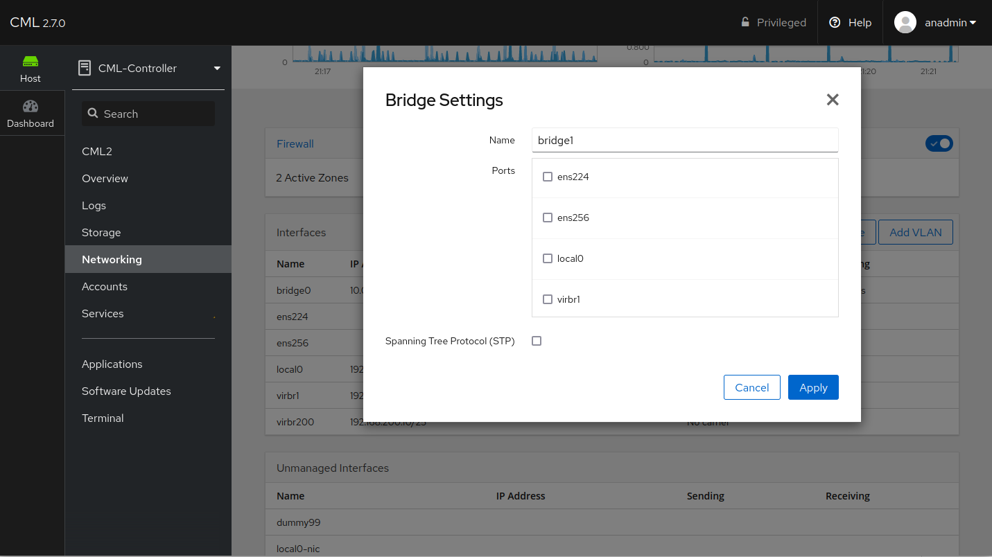
Bridge Create Dialog
By default, the new bridge interface will be auto-configured via DHCP. Since you did not assign the ethernet interface as a member port yet, it cannot get any configuration from the outside.
Click on the newly-created bridge name in the Interfaces table.
Click the Automatic (DHCP) link to open the IPv4 settings dialog.
Turn the configuration method to Disabled, and turn all toggles to the off position.
Click Apply.
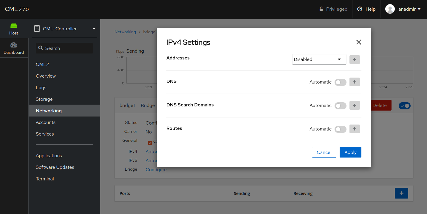
IPv4 Settings dialog
Repeat this for the IPv6 settings, where you set the configuration method to Ignore.
In the Ports table, click on the Plus button and select the desired ethernet interface.
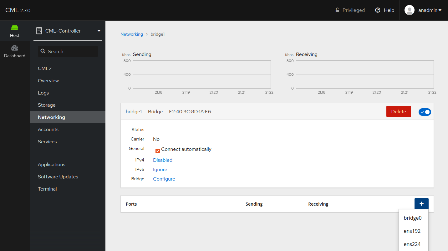
Add a Member Interface to the Bridge
Click on the interface entry in the Ports table. Enable the interface if it is not.
(Optional) If your use case demands, and your network outside of CML can handle it, set a specific MTU on the interface, e.g., 9000. Otherwise, leave it as Automatic.
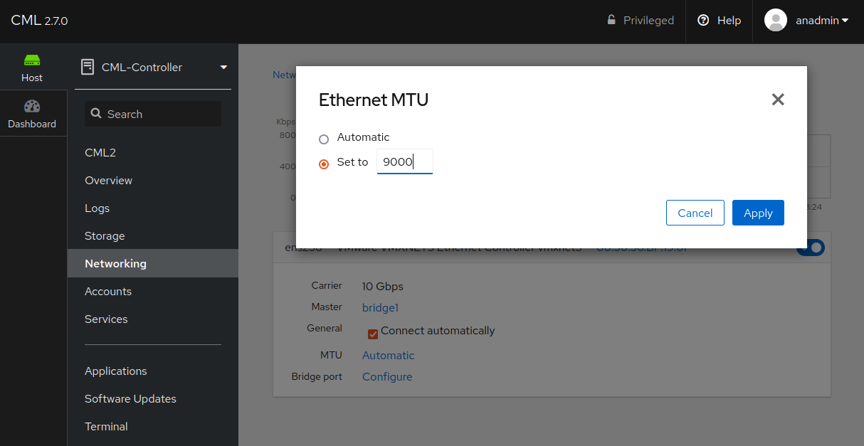
MTU Settings Dialog
The MTU of the bridge will be the lowest MTU of any member port. Since the interface inserted by CML server into the bridge for each lab interface has a nominal MTU set to 9000, the MTU of the associated ethernet port determines the bridge MTU.
Note that lab nodes need configuration to use a larger MTU using methods appropriate for their node type. The nominal MTU of 9000 is not visible to the lab node, and it will use its own defaults.
In VMWare-based deployments, return to VMware UI the Virtual Machine settings. Locate the newly-added interface again and check the Connected check box and the Connect at ower on check box.
The new bridge interface is now created and configured on the CML server. Repeat the process for any additional bridges, then continue with configuring the bridge using the Configuration of External Connector Bridges section of this Admin Guide.