Overview
This module describes the architecture, design options, and best practices to achieve network integration between the edge of the Internet of Things (IoT) fabric and enterprise networks.
Headend design:
- Headend router options (virtual and physical appliances) to achieve different levels of scalability
- Resiliency, redundancy, high-availability, and load balancing
Edge gateway design:
- Options for achieving WAN redundancy
- Edge gateway routing options:
- Split tunnel—Only traffic destined to enterprise networks traverses the tunnel. All other traffic is routed directly to the internet.
- Full tunnel—All traffic (enterprise bound and internet bound) is tunneled back to the enterprise headquarters.
Requirements
- Secure connectivity from the edge devices to the enterprise headquarters
- Extend reachability of enterprise networks and services to the edge of the IoT fabric
- Redundancy, high-availability, and load balancing for edge-to-enterprise connectivity
- Ability for edge devices and sensors to securely send data to applications and analytics software running within the enterprise headquarters
- Access to management systems deployed at the enterprise headquarters
- Ability to support either a full tunnel or split tunnel from the edge gateway
- Ability to advertise only specific enterprise networks to the edge gateway
- Ability to leverage corporate security tools and policies for data access at the edge
Architecture
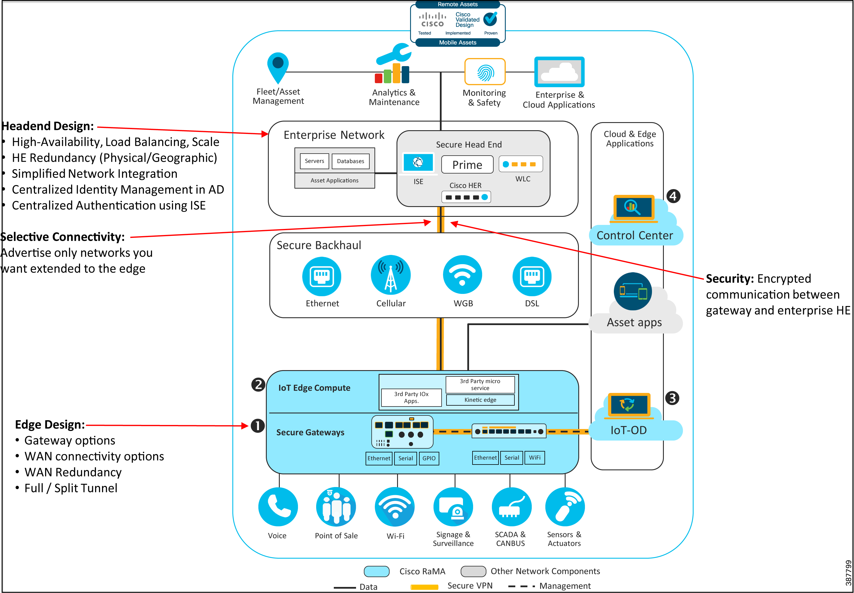
Figure 1: Enterprise Network Integration Architecture
Refer to Remote and Mobile Assets (RaMA) Security for the complete security recommendations including the use of FlexVPN for the enterprise network integration.
The architecture diagram in Figure 1 highlights support for use cases that require extending enterprise network access in a highly secure manner to the edge of the IoT fabric. This architecture utilizes secure FlexVPN connectivity from the edge gateways to a cluster of VPN aggregators within the enterprise data center. This is optimal for enterprises that need to transfer sensitive and confidential information between edge devices and corporate headquarters or need to securely extend access to the edge for certain enterprise networks or services.
Design
VPN Headend Design
To securely extend enterprise connectivity from the enterprise headquarters to the edge gateways, this solution uses secure IPSec/FlexVPN connectivity. The components required to implement the enterprise headend portion of the design include:
- A cluster of highly available, redundant, and scalable routers to terminate the incoming FlexVPN connections from the edge gateways.
- Ability to integrate with Cisco ISE and AD for centralized identity management and authentication of IPSec VPN sessions.
- Optional Integration with enterprise DNS and IPAM servers.
Choice of Headend Router Platforms
Cisco offers several headend router options depending on scalability requirements:
- Small deployments—For a pilot deployment or one involving a few hundred gateways, we recommend using a cluster of Cisco Catalyst 8000V or Cisco CSR 1000v virtual appliances at the headend to terminate the FlexVPN connections coming in from the edge gateways.
- Medium deployments—For a deployment involving a few hundred to a couple thousand edge gateways, we recommend using a cluster of the physical Cisco ISR 4000 series, Cisco ASR 1000 series, orCisco Catalyst 8000 series that provide higher scale and throughput capabilities.
- Large deployments—For a deployment scaling to thousands of edge gateways, we recommend using a cluster of the physical Cisco Catalyst 8000 series or Cisco ASR 1000 series of routers that provide extreme scalability and throughput capabilities.
Figure 2: FlexVPN Scalable Headend Architecture—Platform Choices

VPN Headend Resiliency Options
Multiple methods are available to support VPN resiliency at the enterprise headquarters. As detailed in IKEv2 Load Balancing, this design proposes the use of a cluster of headend routers running Hot-Standby Router Protocol (HSRP) and Internet Key Exchange Protocol version 2 (IKEv2) load balancing to provide VPN resiliency at the enterprise headquarters.
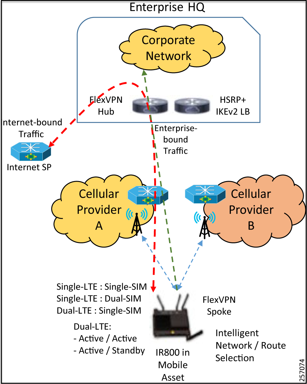
Embedded Event Manager (EEM) scripts can be used on the gateway to trigger SIM failover to provide redundancy for WAN cellular links. This is especially useful with Dual-LTEs or Dual-SIMs.
The following sections describe design options to achieve headend redundancy and high-availability. For this CVD we validated Option 2, which provides physical site redundancy.
Figure 3: Option 1—Geographical Redundancy
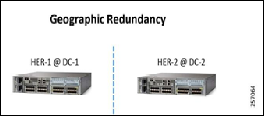
- Locate the first headend router (HER), HER-1 @ DC1 @ Location-1.
- Locate the second HER-2 @ DC2 @ Location-2.
- Configure a different Pre-Shared Key (PSK) on each of the HERs.
- Configure each HER and the remote gateway to use BGP over the tunnel interface. Utilize “Local Preference” to make one HER advertise the datacenter routes more favorably.
- In the IOT Operations Dashboard Template, configure the HER-1 with its PSK and HER-2 with its PSK.
- In this option, both tunnels (to HER-1 and HER-2) will be active simultaneously. In the event of a HER-1 failure, BGP will quickly identify the failure and advertise the datacenter routes over the remaining tunnel.
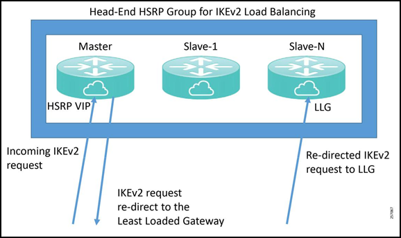
Figure 4: Option 2—Physical Site Redundancy
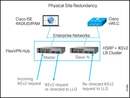
- HSRP and IKEv2 load balancing cluster
- Single primary node
- N-number of secondary nodes
- Primary keeps track of load on each secondary
- Incoming IKEv2 request re-directed to the Least Loaded Gateway (LLG)
Enterprise Network Integration
Figure 5: Simplified Enterprise Network Integration
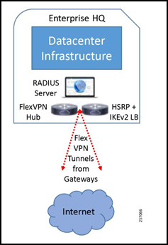
The core network components include:
- Data center infrastructure—This includes compute resources and networking resources like switches and routers, WLC, and enterprise firewalls.
- VPN headend—VPN headend cluster design and implementation to support scalability, redundancy, high-availability, and load balancing of incoming VPN sessions.
- RADIUS server—Enterprise RADIUS server for IEEE 802.1X authentication.
For the CVD, we validated the design with both a pair of Cisco CSR 1000v virtual appliances and a pair of Cisco ASR 1002-HX physical appliances.
For information about the Cisco CSR 1000v virtual appliance, refer to: https://www.cisco.com/c/en/us/products/routers/cloud-services-router-1000v-series/index.html
For information about the Cisco ASR 1XXX models, refer to: https://www.cisco.com/c/en/us/products/routers/asr-1000-series-aggregation-services-routers/index.html
For information about the Cisco Catalyst 8000 models, refer to: https://www.cisco.com/c/en/us/products/routers/cloud-edge/index.html#/
For information about Cisco ISE, refer to: https://www.cisco.com/c/en/us/products/security/identity-services-engine/index.html
For a more detailed enterprise headquarters network design, refer to: https://www.cisco.com/c/en/us/solutions/design-zone/networking-design-guides.html
Refer to the Cisco Data Center Security recommendations located at: https://www.cisco.com/c/en/us/solutions/enterprise/design-zone-security/index.html
FlexVPN Headend Design
We recommend using a pair of HERs running HSRP and IKEv2 load balancing to provide redundancy and load balancing for incoming Flex VPN sessions from the edge gateways at the enterprise headend side.
For detailed information on configuring IKEv2 load balancing, refer to: https://www.cisco.com/c/en/us/td/docs/ios-xml/ios/sec_conn_ike2vpn/configuration/xe-3s/sec-flex-vpn-xe-3s-book/sec-cfg-clb-supp.html
Figure 6: IKEv2 Load Balancing Cluster Design
IKEv2 Load Balancing
The IKEv2 load balancing feature enables the clustering of a group of routers for high-availability and distribution of incoming IKEv2 sessions among the routers that are part of the cluster. It redirects incoming FlexVPN/IKEv2 client requests to the least-loaded router based on system and crypto load factors.
Prerequisites for IKE-v2 load balancing include:
- For the server-side configuration, the HSRP and FlexVPN server (IKEv2 profile) must be configured.
- For the client-side configuration, the FlexVPN client must be configured.
Benefits of IKEv2 load balancing include:
- The IKEv2 load balancing feature is cost effective and easy to configure.
- A FlexVPN client does not need to know the IP addresses of all the gateways in the cluster. The client only need to know the virtual IP address of the cluster.
- The entire crypto session is redirected to the least-loaded router in the cluster.
IKEv2 clustering provides a redirect mechanism that enables a VPN gateway to redirect a FlexVPN client request to another VPN gateway based on load condition and maintenance requirements. This redirect mechanism is performed in the following scenarios:
- On security association (SA) initialization (IKE_SA_INIT)
- On SA authentication (IKE_AUTH)
The IKEv2 load balancer feature provides a Cluster Load Balancing (CLB) solution by redirecting requests from remote access clients to the LLG in the HSRP group or cluster. The CLB solution works with the IKEv2 redirect mechanism defined in RFC 5685 by redirecting requests to the LLG in the HSRP cluster.
Figure 7: IKEv2 Clustering with HSRP Failover to Standby
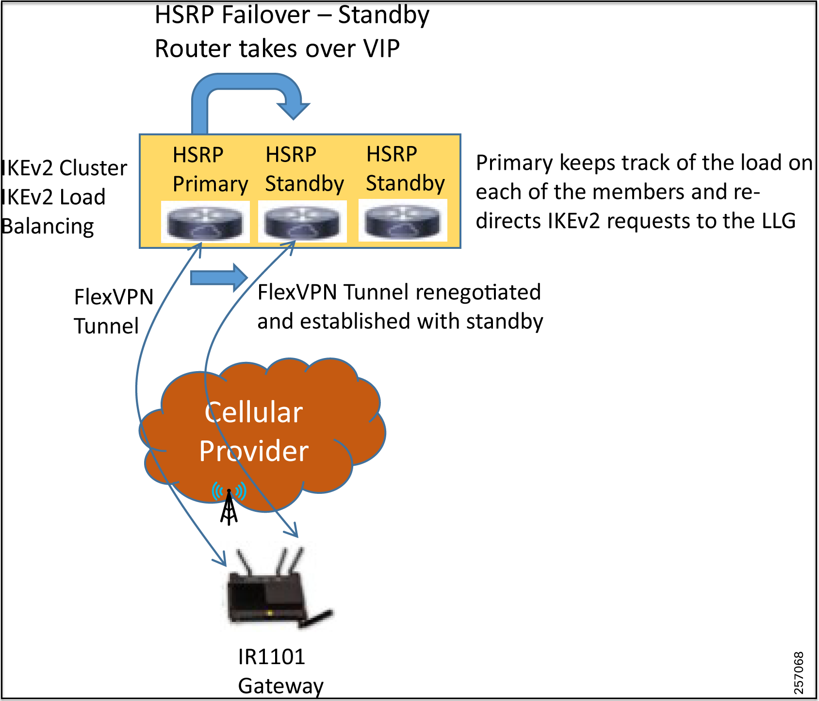
Cluster load balancing occurs in three steps:
- An active HSRP gateway is elected as a “primary” in the HSRP group and takes ownership of the Virtual IP address (VIP) for the group. The primary maintains a list of gateways in the cluster, keeps track of the load on each gateway, and redirects the FlexVPN client requests to the LLG.
- The remaining gateways, termed “secondary”, send load updates to the primary at periodic intervals.
- When an IKEv2 client connects to the HSRP VIP, the request first reaches the primary, which in turn redirects the request to the LLG in the cluster.
The components of the CLB solution are:
- Hot-Standby Router Protocol (HSRP)
- CLB primary
- CLB secondary(s)
- CLB communication
- IKEv2 redirects mechanism
Hot-Standby Router Protocol
HSRP is a Cisco standard for providing high network availability by providing first-hop redundancy for IP hosts on an IEEE 802 LAN configured with a default gateway IP address. HSRP routes IP traffic without relying on the availability of any single router. It enables a set of router interfaces to work together to present the appearance of a single virtual router or default gateway to the hosts on a LAN. When HSRP is configured on a network or segment, it provides a virtual Media Access Control (MAC) address and an IP address that is shared among a group of configured routers. HSRP allows two or more HSRP-configured routers to use the MAC address and IP network address of the virtual router. The virtual router represents the common target for routers that are configured to provide backup to each other. One of the routers is selected to be the active router and another to be the standby router, which assumes control of the group MAC address and IP address should the designated active router fail. Routers in an HSRP group can be any router interface that supports HSRP, including routed ports and SVIs.
HSRP detects when the designated active router fails, and a selected standby router assumes control of the Hot Standby group’s MAC and IP addresses. A new standby router is also selected at that time if one is available. Devices running HSRP send and receive multicast UDP-based hello packets to detect router failure and to designate active and standby routers. When HSRP is configured on an interface, Internet Control Message Protocol (ICMP) redirect messages are automatically enabled for the interface.
The tested design used dual Cisco CSR 1000v virtual appliances in combination with HSRP, which provides redundancy, resiliency, and high availability for FlexVPN tunnels coming in from the edge gateways. A failure of the primary HSRP router causes one of the standby secondary routers, which is part of the HSRP group, to take over as the primary and take ownership of the VIP address. Any FlexVPN sessions that were terminating on the failed primary are renegotiated and established to the remaining routers that are part of the HSRP/IKEv2 load balancing group based on the load on each of the gateways. The newly assumed primary node will monitor the load on each of the gateways that are part of the group and accordingly load balance the IKEv2 requests.
CLB Primary
A CLB primary runs on the HSRP primary or “Active Router” (AR). The primary receives updates from CLB secondarys and sorts them based on their load condition to calculate the LLG. The primary sends the IP address of the LLG to IKEv2 (on the FlexVPN server). The IP address is sent to the initiator (FlexVPN client), which initiates an IKEv2 session with the LLG. The primary redirects incoming IKEv2 client connections towards the LLG.
CLB Secondary
A CLB secondary runs on all devices in an HSRP group except on the AR. The secondarys are responsible for sending periodic load updates to the primary. A CLB secondary is a fully functional IKEv2 gateway which supplies information to the CLB primary. Apart from updates, CLB secondarys send messages for aliveness assurance to the CLB primary.
CLB Load Management Mechanism
The CLB Load Management Mechanism, which is a TCP-based protocol running between the CLB primary and the CLB secondarys, informs the CLB primary about the load on the CLB secondarys. Based on this information, the CLB primary selects the LLG to handle the session for each new incoming IKEv2 connection.
Edge Gateway Design
Gateway Cellular Redundancy Options
- Dual-LTE—This deployment model provides the highest resiliency with the use of two separate cellular radios each with their own SIM card from two separate providers.
- Single-LTE Dual-SIM—This deployment model provides resiliency by allowing the use of a backup service provider using a second SIM.
- Single-LTE Single-SIM—This deployment model does not provide any form of VPN resiliency since it uses a single LTE connection with a single service provider.
Options for Edge Gateway Routing
Option 1—Split Tunnel
In this option, a split tunnel is used for traffic originating from devices behind the gateway. Traffic destined for the public internet is directly sent over the cellular interface out to the internet. The only traffic that traverses the FlexVPN tunnel is for the subnets that are advertised by the enterprise HER to the edge gateways. The advantage of this design is that it reduces the throughput needed at the enterprise headend since it does not need to process traffic intended for the internet. The downside is that all traffic intended for the internet will be allowed. This design is suited for enterprises that want to forward all internet bound traffic directly to the internet without any inspection, filtering, blocking, or application of any other security policies.
Figure 8: Split Tunnel Routing at Edge Gateway

Option 2—Full Tunnel—Default Route Advertised by Enterprise Headend
When using this routing option, a default route is advertised by the enterprise HER and all traffic from the edge devices are first routed to the enterprise HERs. This scenario can be implemented by enterprises that have strict network policies requiring total control over and requirements to inspect and filter all traffic. In this scenario, enterprise firewall rules can be applied and enforced within the enterprise data center before the traffic is forwarded to its intended destination. Unintended traffic can even be blocked and discarded. The same is true for traffic destined for the public internet.
This architecture allows the enterprise to route the traffic via a Web-Application Firewall (WAF) before routing the traffic to the public internet and apply and enforce rules regarding traffic that can be forwarded to the internet. The disadvantage of this design is that since all traffic is first routed to the enterprise headend, it needs to be able to support much higher throughput rates as compared to the split-tunnel design. The advantage is that the enterprise gains control over all traffic originating from the edge, both enterprise bound, and internet bound, and can apply policies (firewall rules, WAF rules) to restrict and filter traffic.
Figure 9: Default Route towards Enterprise Headend
Both options provide control over which enterprise subnets are visible to the edge devices by advertising only those subnets towards the edge gateway.
Best Practices
FlexVPN Headend Router Deployment Best Practices
- Deploy each of the Cisco CSR 1000v virtual appliances on separate virtualization hosts—possibly in separate racks— to protect against underlying host failure or power failure for a particular rack.
- For the physical Cisco ASR 100X routers, use applicable high-availability technologies like IOS-XE process redundancy, dual-route processors (RPs) for hardware control-plane redundancy, and dual ESPs.
- For the physical Cisco ASR 100X routers, it is best practice to deploy each physical appliance in a separate rack attached to a different power supply strip. It is also highly recommended to have dual power supplies in each of the physical routers connected to two different power strips within the rack to provide resiliency against failure of a particular power supply or an entire power strip.
- We recommend using a pair of HERs running HSRP and IKEv2 load balancing to provide redundancy and load balancing for incoming Flex VPN sessions from the edge gateways at the enterprise headend side.
General Best Practices
- Configure a meaningful name for the gateway in IOT Operations Dashboard (e.g., Bus-1234, Robot-456, Machine-11, etc.) that helps with identification, management, and troubleshooting.
- Create a DNS entry for each gateway with a meaningful name pointing to the data tunnel IP address. Again this will help IT and field technicians to refer to the gateway by a meaningful name and be able to connect to the gateway using its DNS name rather than having to consult an Excel sheet or inventory management system to determine the data tunnel IP address for that gateway (e.g., ssh admin@Bus-1234).
Appendix—Implementing Integration with ISE
When a gateway tries to connect to the customer’s data center, it is important to make sure that the gateway has permission to do so. Otherwise, unwanted devices could remotely gain access to the data center and allow someone to seriously damage the data center.
In the previous version of RAMA, the establishment of FlexVPN tunnels between gateways and the headend router (HER) was handled entirely by the HER. The authentication and authorization were both performed via local pre-shared key and the gateway tunnel IP address was supplied by a DHCP pool configured on the HER. This method benefited from ease of setup (only the HER was required to configure manually), but some of the downsides included:
- Not scaling well since specific CLI configuration would be required for every gateway.
- Network rules were limited to the capabilities of the HER.
- Device management was all CLI based.
This appendix presents the steps for allowing FlexVPN tunnels to instead be authenticated, authorized, and configured through a combination of ISE, Windows Active Directory (AD), and Cisco Prime Network Registrar (CPNR). The benefits of this design are:
- The external pieces are easily managed.
- Scales well.
- Enhanced customizability and security. The logical flow of this design is as follows:
Figure 10: FlexVPN Tunnel Initialization Flow

- The tunnel is first authenticated locally via pre-shared key. The gateway and HER will check against the locally configured keyrings.
- Once the initial authentication is successful, the HER will send an authorization request to ISE. This request will include a pre-shared key defined on the HER, as well as a username that is obtained from IKEv2 communication between the gateway and the HER.
- ISE receives the authorization request and makes sure it is sent from an accepted network device. Once this has been verified, ISE takes the username/password it receives and queries AD to make sure they are valid. 4.ISE then authorizes the network connection, telling the HER to forward DHCP requests to CPNR. The CPNR then offers the next available IP address to be applied to the gateway tunnel interface, completing the flow.
The following sections assume that all systems have already been installed and focuses strictly on the relevant configuration for:
- IR 829 (gateway) via IoT Operations Dashboard
- HER (ASR 1000)
- ISE
- AD
- CPNR
IR 1101 IOT Operations Dashboard FlexVPN Configuration
There is nothing that needs to be done differently on the gateway to support this scenario (compared to the previous version). To configure the Site-To-Site VPN using an eCVD based template:
- Enable “Primary Headend” in the template.
- Enter the Public IP Address of the HER.
- Enter the Pre-shared key to be used.
- Claim the gateway specifying this template.
Figure 11: Site-To-Site VPN in IOT Operations Dashboard

HER Configuration
The HER serves as the FlexVPN hub. All desired gateways configured for site-to-site VPN will try to establish a connection with this hub and the major configuration sections are as follows:
- AAA
- Loopback Interface
- Virtual-Template
- IKEv2 Name-Mangler
- IKEv2 Profile
AAA
The AAA configuration is responsible for defining:
- Local and Remote authentication/authorization
- The RADIUS Server (ISE) for remote authentication/authorization
- Interface to use for ISE communication
aaa aaa new-model
!
!
aaa group server radius ISE
server name ISE24
ip radius source-interface Port-channel1.30
!
aaa authentication login default local
aaa authorization exec default local none
aaa authorization network FLEX group ISE
aaa accounting network FLEX start-stop group ISE
!
!
aaa server radius dynamic-author client
ISE_ADDRESS server-key PASSWORD
!
aaa session-id common
!
!
radius-server attribute 6 on-for-login-auth
radius-server attribute 6 support-multiple
radius-server attribute 8 include-in-access-req
radius-server dead-criteria time 20 tries 2
radius-server deadtime 1
!
radius server ISE24
address ipv4 ISE_ADDRESS auth-port 1645 acct-port 1646
key PASSWORD
!
Loopback Interface
The loopback interface serves as the source interface for all the FlexVPN tunnels.
interface Loopback0
ip address IP_ADDRESS NETMASK
ip mtu 1400
!
Virtual-Template
Whenever the gateway tries to form a tunnel with the HER, a virtual tunnel interface will be created from referencing the virtual template.
interface Virtual-Template1 type tunnel
ip unnumbered Loopback0
ip mtu 1400
ip nat inside
ip nhrp network-id 2
ip nhrp redirect
ip tcp adjust-mss 1360
tunnel mode ipsec ipv4
tunnel path-mtu-discovery
tunnel protection ipsec profile default
ISE will supply additional configuration for the created virtual tunnel interface during the authorization process.
IKEv2 Name Mangler
The name-mangler extracts the username from the email address provided during local authentication. It is then used in the authorization request to ISE. As mentioned in Design, real world use cases may want to use a different string as the username (such as the vehicle ID, robot ID, etc.) instead of the gateway’s serial number (as is shown in this example). We recommend using a custom EEM script to extract this ID from the connected device and change the IKEv2 local identity configuration on the gateway.
crypto ikev2 name-mangler PSK
email username
IKEv2 Profile and IKEv2 Keyring
The authorization profile is used to define the authentication/authorization mechanisms based off the email domain in the IKEv2 messages from the gateway. The authentication method is pre-shared key via a local keyring, while the authorization method is a request to ISE (containing the name-mangler username and a predefined password). Note: A user account must be created on AD that matches the username /password since ISE is going to reference AD instead of a local ISE database.
crypto ikev2 profile Flex_IKEv2
match fvrf any
match identity remote email domain iotspdev.io
identity local key-id public_ip_address
authentication remote pre-share
authentication local pre-share
keyring local field_keys
dpd 250 10 on-demand
aaa	authorization user psk list FLEX name-mangler PSK password
AD_password aaa accounting psk FLEX
virtual-template 1
!
crypto ikev2 keyring field_keys
peer SIMULATED
identity email domain iotspdev.io
pre-shared-key password
!
!
Sample Configuration
!
version 16.9
service timestamps debug datetime msec
service timestamps log datetime msec
platform qfp utilization monitor load 80
no platform punt-keepalive disable-kernel-core
!
hostname ASR1K-A-Top
!
boot-start-marker
boot-end-marker
!
!
vrf definition Mgmt-intf
!
address-family ipv4
exit-address-family
!
address-family ipv6
exit-address-family
!
enable password lab
!
aaa	new-model
!
!
aaa group server radius ISE server name ISE24
ip radius source-interface Port-channel1.30
!
aaa authentication login default local
aaa authorization exec default local none
aaa authorization network FLEX group ISE
aaa accounting network FLEX start-stop group ISE
!
!
aaa server radius dynamic-author client
ISE_IP server-key ISE_PASSWORD
!
aaa session-id common
!
!
ip name-server DNS_IP
ip name-server vrf Mgmt-intf DNS_IP
ip domain lookup source-interface Port-channel1.251
!
!
subscriber templating
!
!
multilink bundle-name authenticated
!
!
crypto pki	trustpoint TP-self-signed-3103357051
enrollment selfsigned
subject-name cn=IOS-Self-Signed-Certificate-3103357051
revocation-check none
rsakeypair TP-self-signed-3103357051
!
!
crypto pki	certificate chain	TP-self-signed-3103357051
certificate self-signed 01
30820330    30820218    A0030201    02020101    300D0609    2A864886    F70D0101    05050030
31312F30    2D060355    04031326    494F532D    53656C66    2D536967    6E65642D    43657274
69666963    6174652D    33313033    33353730    3531301E    170D3139    30323138    31323039
30345A17    0D333030    31303130    30303030    305A3031    312F302D    06035504    03132649
4F532D53    656C662D    5369676E    65642D43    65727469    66696361    74652D33    31303333
35373035    31308201    22300D06    092A8648    86F70D01    01010500    0382010F    00308201
0A028201    0100CD21    042E0780    271C5A8B    6F7B6CE3    E0230BB0    08F93AA0    01AEC893
05B6DC4D    F3F753AD    8B22C44B    C4C41C97    19F2B197    051D4C12    026256CA    5163957B
DA825C78    457CDA8B    31D4A75C    74F3AF5B    CA66DDE3    E0C65DAF    0445F741    CE84732A
42F25D5E    41EDACFE    87B7E24C    32936A23    F74FE1C7    2C404C2A    FF908B63    2FB76560
E0F3FDE0    4E880475    34B35E3E    F791DD9F    C2579785    D359FC92    985B9701    B38A0498
85B03F72    5EEAA566    BB849ECF    0C0CF72C    79FBCB43    030018C5    6867676F    5E0A5BC5
9E17761D    9C1717BA    96DC3E99    F4922D51    3CB56661    E51A0769    049BCAF1    226EC2D5
768C91D7    F378E6E4    1B088E1C    E871842D    447A5889    265FD06C    D1DEAA12    35F0ABE7
8E6128D8    13510203    010001A3    53305130    0F060355    1D130101    FF040530    030101FF
301F0603    551D2304    18301680    147DC873    4CC0BD1C    AAE5558A    470C2E56    BE53FA4B
AD301D06    03551D0E    04160414    7DC8734C    C0BD1CAA    E5558A47    0C2E56BE    53FA4BAD
300D0609    2A864886    F70D0101    05050003    82010100    18BC525B    2628D6CB    FC1582CA
5DF46D43    1DDFADC2    D63A3342    0A09FD5C    978C157F    79426760    C74C6D19    729C1EB9
3DB33A70    6ECDC246    828C558B    05F13C6D    D48CA048    D5F6E0E1    E6A4F205    7C831ED5
367C457A    D083F49E    2ADA3ED5    4533F433    FFE76C0F    D94E999F    89044040    E38AA5E5
CC483320    2CBA5962    F4F999E8    49AC2533    F2D43419    93C2B54D    578E6D03    5670A9E2
F82AE545    263F1438    E82D12AE    14DD496C    7747A9F8    B9FF7F78    54FCDCA7    90974585
1B951E27    337D5721    7CA38D99    EF84882E    EB35325E    572F5F72    C1E7BD79    057C6B24
540B11B2    F887B298    A31A02EF    CC1934D6    BADF67D3    656C34DC    ABC1B154    FF9D3549
477F9AB4    91537DA4    848A9F0B    EC34AED9    597966E5
quit
!
license udi pid ASR1002-HX sn JAD23030BSP
license accept end user agreement
license boot level adventerprise
no license smart enable
!
spanning-tree extend system-id
diagnostic bootup level minimal
!
!
username USERNAME privilege 15 password 0 PASSWORD
!
redundancy
mode none
!
crypto ikev2 name-mangler PSK
email username
!
crypto ikev2 authorization policy default
route set interface
route set access-list CLOUD
!
crypto ikev2 authorization policy IXIA_AUTH_POLICY
pool IxiaPool
route set interface
!
crypto ikev2 authorization policy IXIA_AUTH_POLICY2
pool IxiaPool2
route set interface
!
crypto ikev2 redirect gateway init
!
!
crypto ikev2 keyring field_keys
peer SIMULATED
identity email domain iotspdev.io
pre-shared-key PASSWORD
!
!
!
crypto ikev2 profile Flex_IKEv2
match fvrf any
match identity remote email domain iotspdev.io
identity local key-id PUBLIC_IP
authentication remote pre-share
authentication local pre-share
keyring local field_keys
dpd 250 10 on-demand
aaa	authorization user psk list FLEX name-mangler PSK password
AD_PASSWORD aaa accounting psk FLEX
virtual-template 1
!
!
crypto ikev2 reconnect key 1 active cisco12345
!
crypto ikev2 cluster
standby-group dmz-group
slave max-session 10000
no shutdown
!
!
!
track 1 ip route 10.0.2.1 255.255.255.255 reachability
!
track 2 list boolean and
object 1 not
!
cdp run
!
!
interface Loopback0
ip address 10.5.0.1 255.255.0.0
ip mtu 1400
!
interface Port-channel1
no ip address
no negotiation auto
!
interface Port-channel1.1
!
interface Port-channel1.30
encapsulation dot1Q 30
ip address 10.2.0.2 255.255.0.0
ip nat inside
standby 30 ip 10.2.0.1
!
interface Port-channel1.77
encapsulation dot1Q 77
ip address 77.77.77.2 255.255.255.0
ip nat inside
standby 77 ip 77.77.77.1
!
interface Port-channel1.251
encapsulation dot1Q 251
ip address PUBLIC_IP NETMASK
ip nat outside
ip access-group BLOCK_TELNET_SSH in
!
interface GigabitEthernet0/0/0
no ip address
negotiation auto
channel-group 1
!
interface GigabitEthernet0/0/1
no ip address
negotiation auto
channel-group 1
!
interface GigabitEthernet0/0/2
no ip address
shutdown
negotiation auto
!
interface GigabitEthernet0/0/3
no ip address
shutdown
negotiation auto
!
interface GigabitEthernet0/0/4
no ip address
shutdown
negotiation auto
!
interface GigabitEthernet0/0/5
no ip address
shutdown
negotiation auto
!
interface GigabitEthernet0/0/6
no ip address
shutdown
negotiation auto
!
interface GigabitEthernet0/0/7
no ip address
shutdown
negotiation auto
!
interface GigabitEthernet0
vrf forwarding Mgmt-intf
ip address 10.100.5.7 255.255.0.0
negotiation auto
!
interface Virtual-Template1 type tunnel
ip unnumbered Loopback0
ip mtu 1400
ip nat inside
ip nhrp network-id 2
ip nhrp redirect
ip tcp adjust-mss 1360
tunnel mode ipsec ipv4
tunnel path-mtu-discovery
tunnel protection ipsec profile default
!
router ospf 1
router-id 10.1.0.2
redistribute connected subnets
redistribute static subnets
network 77.77.77.0 0.0.0.7 area 0
default-information originate
!
ip nat inside source list PAT-LIST interface Port-channel1.251 overload
ip forward-protocol nd
no ip http server
ip http authentication local
ip http secure-server
ip tftp source-interface GigabitEthernet0
ip route 0.0.0.0 0.0.0.0 GATEWAY_IP
ip route 10.10.2.0 255.255.255.0 10.10.1.4
ip route 10.11.0.0 255.255.0.0 10.10.0.4
ip route 10.14.0.0 255.255.0.0 10.10.3.4
ip route 10.50.0.0 255.255.0.0 10.100.0.1
ip route 10.100.0.0 255.255.0.0 GigabitEthernet0
ip route vrf Mgmt-intf 0.0.0.0 0.0.0.0 10.100.0.1
!
ip scp server enable
!
!
ip access-list standard CLOUD
permit	10.2.0.0	0.0.255.255
permit	10.5.0.0	0.0.255.255
permit 10.50.0.0 0.0.255.255
ip access-list standard VPN_CLIENTS
permit	10.0.0.0 0.255.255.255
permit	172.17.92.0 0.0.0.255
permit 100.0.0.0 0.255.255.255
permit 192.168.0.0 0.0.0.255
permit 10.2.0.0 0.0.255.255
!
ip access-list extended BLOCK_TELNET_SSH
deny	tcp any any eq 22
deny	tcp any any eq telnet
permit ip any any
ip access-list extended PAT-LIST
permit ip 10.2.0.0 0.0.255.255 any
permit ip 172.17.92.0 0.0.0.255 any
permit ip 192.168.0.0 0.0.0.255 any
permit ip 10.5.0.0 0.0.255.255 any
permit ip 192.169.0.0 0.0.0.255 any
permit ip 10.0.0.0 0.0.255.255 any
permit ip 192.168.5.0 0.0.0.255 any
!
!
!
!
radius-server attribute 6 on-for-login-auth
radius-server attribute 6 support-multiple
radius-server attribute 8 include-in-access-req
radius-server dead-criteria time 20 tries 2
radius-server deadtime 1
!
radius server ISE24
address ipv4 ISE_IP auth-port 1645 acct-port 1646
key PASSWORD
!
!
control-plane
!
!
line con 0
stopbits 1
line aux 0
stopbits 1
line vty 0 4
exec-timeout 360 0
transport preferred none
transport input all
line vty 5 14
transport preferred none
transport input all
!
end
Windows Active Directory
In this scenario, Windows Active Directory is referenced by ISE to determine if the gateway is authorized on the network.
To do this, one must:
- Enable a Windows Machine as an Active Directory Domain Controller.
- Add a “group” that will contain entries for any appropriate gateways.
- Create a “user” entry for each gateway and add it to the group.
Set Up Windows as a Domain Controller
For instructions for setting up Windows Server as a Domain Controller, refer to: https://blogs.technet.microsoft.com/canitpro/2017/02/22/step-by-step-setting-up-active-directory-in-windows-server-2016/
Create an AD Group and User Accounts
To create the requisite AD Group and User accounts:
Open Server Manager.
Select AD DS from the leftmost column, right click the server name, and select Active Directory Users and Computers.
Figure 12: Server Manager AD DS

Expand the domain.
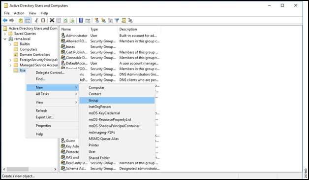
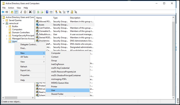
Right click the Users folder.
Navigate to New -> Group.
Figure 13: Active Directory Users and Computers
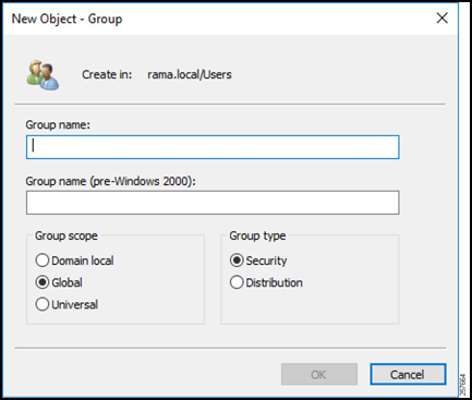
Give the group a name, a scope, and a Security group type. A Security group type is used to provide access to resources, while a Distribution group type is used to create e-mail distribution lists.
Figure 14: Configure the Group
Create Users
Back in the AD Group and User accounts window, right click the Users folder again but navigate to New -> User this time.
Figure 15: Add a User
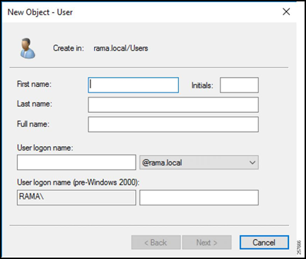
Enter the username that the gateway will send in the authentication request (such as the gateway serial number) for the First Name and User Logon Name fields.
Click Next.
Figure 16: Configure the User’s Name
Enter a password for the user. This password must match the password that will be sent in the authorization request from the HER to ISE. Uncheck User must change password at next login.
Click Next.
Figure 17: Configure the User’s Password

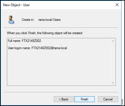
Verify that the information is correct and select Finish.
Repeat for every user.
Figure 18: Finish User Creation
Add Users to Group
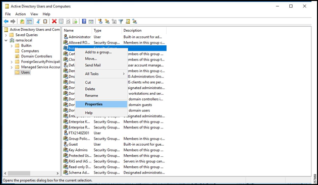
Locate and right-click the previously created group in the Active Directory Users and Computers window.
Select Properties.
Figure 19: Open Group Properties
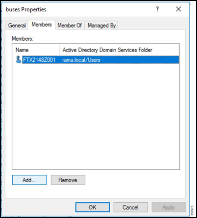
Select the Members tab.
Click Add.
Figure 20: Group Members
Enter the object names of all the users.
Figure 21: Add Members to Group
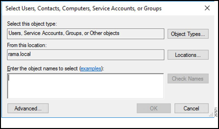
Once all the users have been added, ISE will be able to query the AD group for any username defined in the authorization request and subsequently permit or deny access.
After AD is finished being configured, CPNR must be set up to provide DHCP services for future tunnel connections.
Cisco Prime Network Registrar
The Cisco Prime Network Registrar is used for DHCP services to provide the gateway tunnel interface with an IP address. For the steps to install CPNR, refer to:
Once CPNR is up and running, the DHCP pool must be configured.
Configuring the DHCP Pool
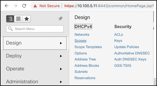
The DHCP pool is going to provide the next available IP address to the gateway tunnel interface once it has been authorized to join the network. To create one:
Navigate to Design -> DHCPv4 -> Scopes.
Figure 22: DHCPv4 Scopes
Click the button to the left of the X to add a scope.
Figure 23: DHCP Scope List

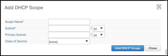
Enter the Scope Name, Subnet, and Primary Subnet.
- The Subnet must match the network of the Tunnel Source Loopback Interface on the HER.
- The Primary Subnet should be the network on which the CPNR is going to be receiving DHCP requests.
Figure 24: Add DHCP Scope
Make sure the mode is Advanced in the top right corner. This will allow for the configuration of specific DHCP options.
Figure 25: Advanced CPNR Configuration

Select Create New Embedded Policy under the newly created DHCP scope.
Figure 26: Create New Embedded Policy

Under DHCPv4 Options select [3] routers (IP address), enter the IP address of the HER loopback interface as the value, and select Add Option. This will provide the gateway tunnel interface with a default gateway pointing to the HER tunnel interface.
Figure 27: DHCPv4 Options

Now that both AD and CPNR are configured, it is time to configure ISE.
ISE Configuration
AD Join Point
Since AD is going to be used as the user database (instead of locally defined users), it must be added to ISE as an AD Join Point. The steps to add an AD Join Point are as follows:
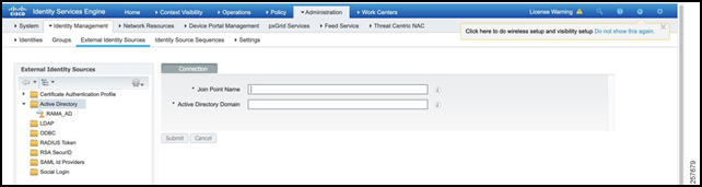
Navigate to Administration -> Identity Management -> External Identity Sources.
Select Active Directory and then click Add.
Figure 28: Add an AD Join Point

Enter the Join Point Name (AD hostname) and the Active Directory Domain. This hostname must be resolvable via DNS in the given domain.
Figure 29: Provide the Name and Domain
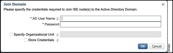
Select the newly created AD Join Point under Active Directory. Tick the box and select Join.
Figure 30: Attempt to Join

Enter the valid AD username and password and click OK.
Figure 31: Specify Username and Password
When the process is complete, the AD Join Point joins, and it is time to add the HER as a Network Device.
Network Devices and Groups
When the authorization request is sent from the HER to ISE, ISE must first check to see if the HER is a trusted device. To do this, a corresponding Device must be created and placed in a Network Device Group. This steps to do so are as follows:
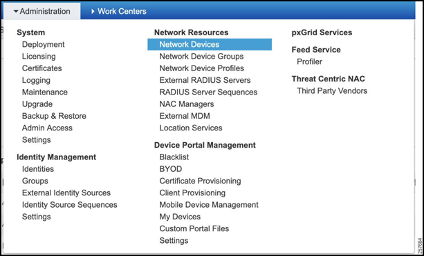
Navigate to Administration > Network Device Groups.
Figure 32: Network Device Groups

Create a new group called FlexVPN_HUBS and nest this under All Device Types.
Figure 33: Add Network Device Group

Navigate to Administration > Network Devices.
Figure 34: Network Devices
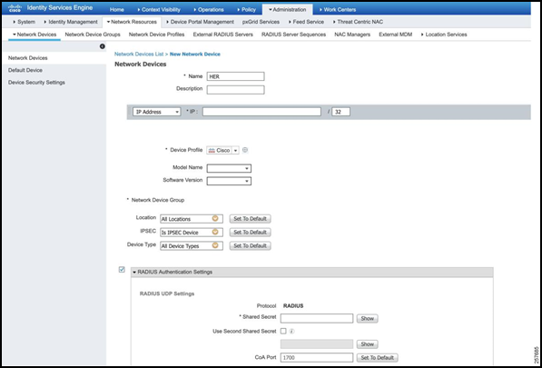
Create a new Network Device.
- Add a descriptive name for the HER.
- Add IP address.
- Select Device Type as FlexVPN_HUBS.
- Tick RADIUS Authentication Settings.
- Specify the Shared Secret as specified in the AAA configuration on the Hub.
- Click Save when complete.
Figure 35: Add a New Network Device
Authorization Profile
The Authorization Profile outlines what actions ISE should take if the Authorization Rule Condition (defined in the Policy Set section) is met. To configure the Authorization Profile:
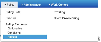
Navigate to Policy -> Policy Sets -> Results.
Figure 36: Navigate to Authorization Profile
Expand Authorization, select Authorization Profiles, and then Add.
Figure 37: Add an Authorization Profile

Give the Authorization Profile a descriptive name and add the below Advanced Attribute Settings.
- cisco-av-pair = ip:interface-config=ip unnumbered TUNNEL_SOURCE_INTERFACE
- cisco-av-pair = ipsec:group-dhcp-server=CPNR_IP_ADDRESS
- cisco-av-pair = ipsec:route-set=interface
- cisco-av-pair = ipsec:route-set=access-list ACL_DEFINED_IN_HER
- cisco-av-pair = ipsec:dhcp-giaddr=HER_TUNNEL_SOURCE_IP
The Advanced Attribute Settings outline configuration that will be used in the Virtual Tunnel Interface that is created as the tunnel is forming.
Figure 38: Authorization Profile Configuration
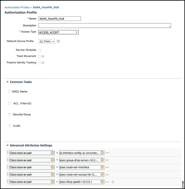
Click Save.
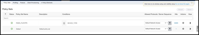
Policy Sets
The policy set will define the logical flow of the authorization request. It will first check against an authentication ruleset for the HER itself to make sure that the HER is permitted. Afterwards (if the authentication is passed), an authorization ruleset will be checked against using the FlexVPN session username and password. Complete these steps to create a policy set:
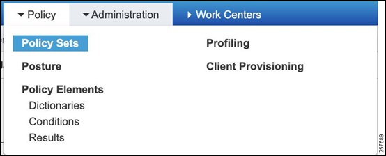
Navigate to Policy -> Policy Set.
Figure 39: Policy Set
Define a new Policy Set with a descriptive name, e.g., RAMA_FLEXVPN.
Figure 40: Create a New Policy Set
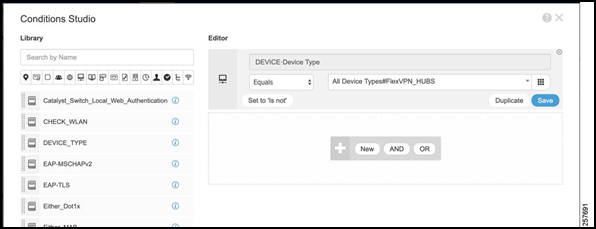
Click the arrow under “view”, expand the “Authentication Policy”, and add an authentication rule.
Specify the Condition as:
DEVICE:Device Type EQUALS All Device Types#FlexVPN_HUBSFigure 41: Authentication Policy Conditions Studio
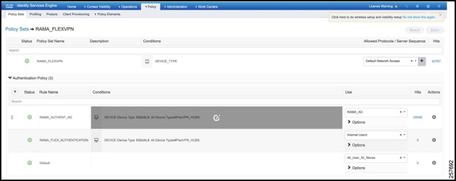
Set the Use value as the AD Joint Point.
Figure 42: Final Authentication Policy
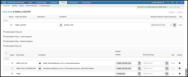
Expand the Authorization Policy.
Add an Authorization Rule.
Specify the Condition as:
RAMA_AD:ExternalGroups EQUALS rama.local/Users/busesThis tells ISE to check if the user is found under the AD Group created in the earlier section.Under Results, select the Authorization Profile that was created earlier.
Figure 43: Final Authorization Policy
Troubleshooting
ISE
The best place to determine the status of the flow is in ISE.
Navigate to Operations -> RADIUS -> Live Logs. This will display a list of all the authorization attempts.
Figure 44: RADIUS Live Logs

Select the latest attempt you would like to inspect. This will display which step that the attempt failed at. This could include such things as:
- Not initiating from a valid network device,
- Not having a matching authentication/authorization ruleset,
- Not finding the gateway in AD
- Etc.
Figure 45: Live Log Overview

Figure 46: Live Log Results

Figure 47: Live Log Steps

Additionally, ISE has a TCP Dump feature to allow for the capture of all packets coming in. This can then be exported as a PCAP file and inspected in Wireshark. To do so, navigate to Operations -> Troubleshoot -> Diagnostic Tools.
Click TCP Dump.
- Select the ISE host.
- Choose the Network Interface that communicates with the HER.
- Select Format type.
Figure 48: TCP Dump

If all steps have succeeded in ISE, then CPNR can be checked to determine whether an appropriate IP address is being leased.
CPNR
The steps to check the DHCP logs in CPNR are as follows:
Select the button at the top left of the page to open a hidden column.
Figure 49: CPNR Dropdown Menu

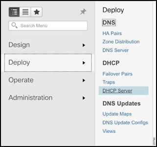
Navigate to Deploy -> DHCP -> DHCP Server.
Figure 50: DHCP Server
Selects Logs.
Figure 51: CPNR Logs
