Mapping Modules for IR Devices
Alert: Cisco has made the end-of-life (EOL) announcement for the Cisco Edge Device Manager (EDM).
Overview
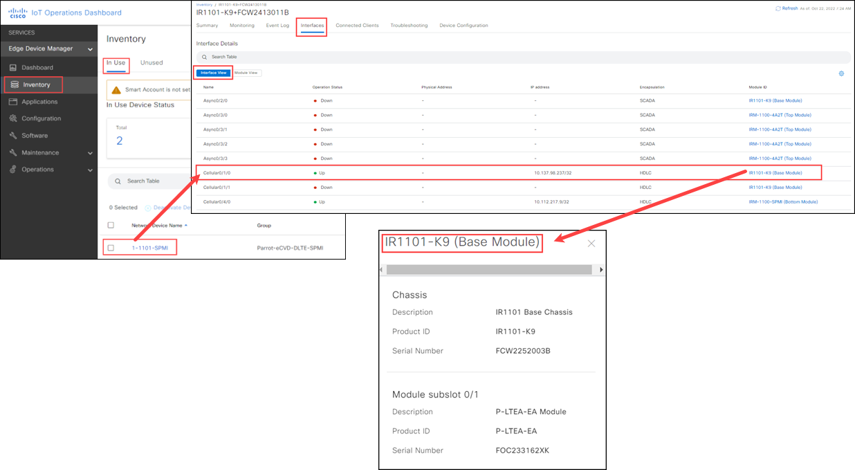
EDM supports an enhanced view of IR device inventory by auto-discovering device modules and interfaces. The modules and interfaces are displayed on the Inventory > Interfaces page.
Click Inventory >Selected Network Device Name > Interfaces tab to view the modules discovered on the devices mapped to your organization. From the Interfaces page, view the modules in the following two ways:
- Module View button: Clicking this button opens all the modules that belong to that device.
- Interface View button: Clicking this button shows all interfaces in a table view with the Module ID column that helps to identify to which module an interface belongs.
Note: In IR829, 809, 807, 1100, and 1800 devices, each chassis is labeled as Base. For the IR1100, each expansion module is labeled as Top and each compute module is labeled as Bottom.
Working in the Interface View page
The Interfaces View page provides an overview of all the device interfaces. It lists:
- Name: Name of the Port
- Admin Status: Lists whether the device is up or down
- Operation Status: Up (green) or Down (Red)
- MAC Address: Lists the MAC Address of the device
- IP address: Lists the IPv4 address used by the device
- Encapsulation: How the device is bundled (for example: protocol, etc.)
- Module ID: Lists the link to the specific module and its details
Open the Interfaces page to view Module ID details:
- In IoT OD, select Edge Device Manager service > Inventory > In Use tab.
- Click the appropriate Network Device Name.
- In the device page, select the Interfaces tab (default view is Interface View).
- In the Module ID column, click the appropriate Module link. The slider opens to show the module details.

Working in the Module View page
Open the Interfaces page and view Module details:
- In IoT OD, select Edge Device Manager service > Inventory > In Use tab.
- Click the appropriate Network Device Name.
- In the device page, select the Interfaces tab and click Module View.
- Click the appropriate Module Details. The slider opens to show the module details for that device.

Wi-Fi WGB plus Hotspot interface information
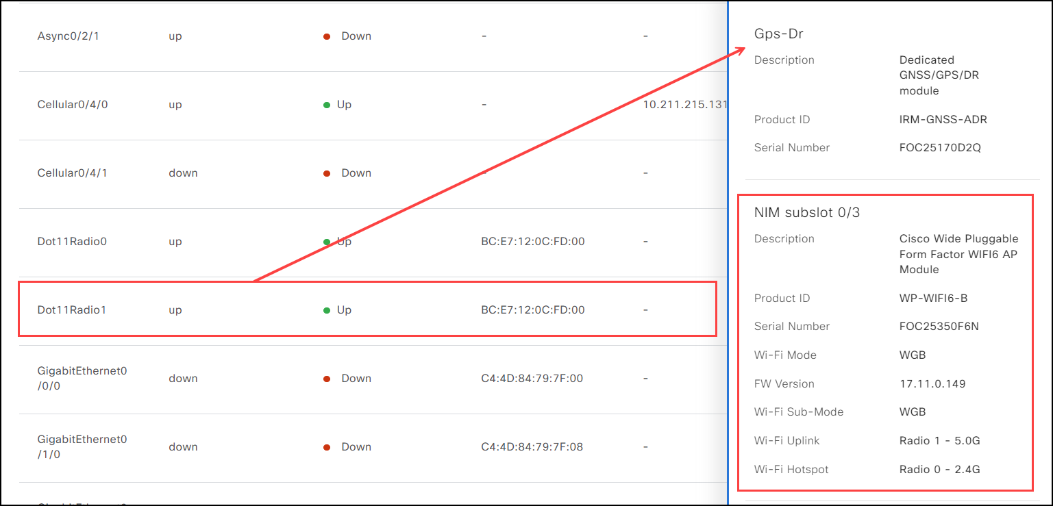
For customers using WGB plus Hotspot there are two specific interfaces, Dot11Radio1 (Wi-Fi Uplink) and Dot11Radio0 (Wi-Fi Hotspot) that show the WGB frequencies used in the Wi-Fi6 configuration. The subslot, NIM subslot 0/3, provides specific configuration information for WGB plus Hotspot. The information is showing what the device is currently reporting to IoT OD.
Note: For specific information on configuring the Wi-Fi6 module, see Wi-Fi settings for the IR1800.
The NIM subslot 0/3 provides this configuration information:
- Description: Provides a short description of the Wi-Fi6 module.
- Product ID: Lists the PID for the Wi-Fi6 module.
- Serial Number: Lists the serial number for the Wi-Fi6 module.
- Wi-Fi Mode: Shows that the Wi-Fi6 module is configured to use WGB.
- FW Version: Lists the firmware version being used. (For WGB plus Hotspot the minimum FW version is 17.11.0.1a or above.)
- Wi-Fi Sub-Mode: Shows the sub mode being used.
- Wi-Fi Uplink: Lists the frequency selected on Dot11Radio1 interface.
- Wi-Fi Hotspot: Lists the frequency selected on Dot11Radio0 interface.
Note: The interface Dot11Radio0 is limited only to the 2.4GHz frequency, but it can be configured for both Wi-Fi Uplink and Wi-Fi Hotspot. On the other hand, the interface Dot11Radio1 gives you the choice or using either 2.4GHz or 5GHz, but it cannot be use 5GHz for both Wi-Fi Uplink and Wi-Fi Hotspot. For more information on Uplink and Hotspot frequencies, refer to Cisco Catalyst IR1800 Rugged Series Router Software Configuration Guide.

Limitations
Periodic metric updates collect module information. Previously onboarded devices have empty module IDs until the next periodic metrics update runs (default interval is 30 minutes).