Overview
This module explains various options and designs for establishing northbound (WAN) or southbound (LAN) connectivity from Cisco industrial gateways deployed in remote sites or mobile applications. The remote connectivity can give remote asset owners and operators in industrial and commercial locations the ability to collect and manage data from machines and devices remotely and can enable new business opportunities, improve efficiencies, and reduce cost. This module contains architectures, design guidance, best practices, and implementation details for robust industrial networks in wired and wireless scenarios at remote sites and mobile assets.
Note: This document covers only the IR1100 and IR1800 series.
Requirements
The following is a list of common requirements that should be considered when making decisions about the gateway networking design and implementation:
WAN Connectivity
- Bandwidth (upstream and downstream)
- Latency, jitter, packet loss tolerance
- Security, including authorization, authentication, integrity, encryption, access control
- Public or private addressing
- Cost
- Redundancy, including failover times
- Availability of wired or wireless service provider
- Routing
- Access to cloud and enterprise networks
- Mounting locations for gateway and antennas
LAN Connectivity
- Types of downstream devices
- Bandwidth
- Power over Ethernet wattage
- Static or dynamic addressing
- Wired or wireless clients
- Connectivity for legacy devices
- Mounting locations for gateway and antennas
Architecture
The Remote and Mobile Assets solution leverages the variety of interfaces and technologies available in Cisco’s industrial router product line to provide connectivity in most use cases where devices in the field need to access the Internet or the enterprise network. As highlighted in Figure 1 below, the RaMA overall architecture includes secure gateways with various methods for providing WAN backhaul and LAN access.
Figure 1: RaMA Gateway Networking Architecture
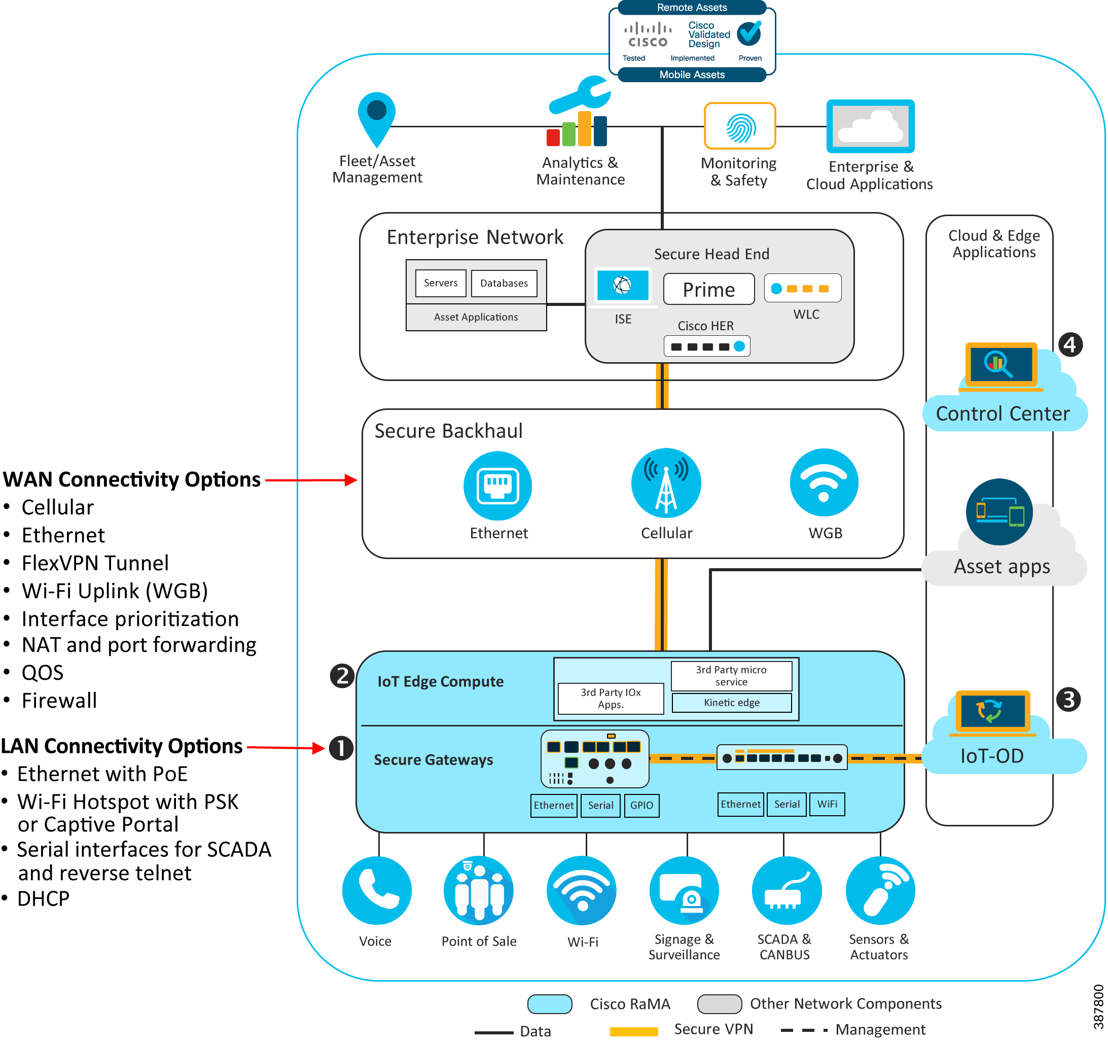
The network architecture covers the following important key points:
WAN Connectivity
WAN technologies generally fall into two categories: wired or wireless. Wired technologies such as Ethernet or DSL are usually preferred at remote fixed locations when possible as they typically provide more predictable performance in terms of throughput, latency, and reliability. Wireless technologies like Cellular and WiFi provide more flexibility for sites where a wired connection is not feasible due to geography, cost, or application (a moving vehicle, for example). Wireless technologies continue to rapidly evolve, and with 5G and WiFi 6 starting to make waves in the market, they provide stiff competition for more traditional wired access technologies. It is important to evaluate the requirements of each use case carefully to determine the best WAN technology. The Design section of this document will dive into the details of the types of WAN connectivity options available, as well as implications for choosing one (or more) of them.
LAN Connectivity
LAN technologies also can be either wired or wireless. Wired technologies include ethernet, serial, or even general-purpose digital IO inputs. In IoT applications, having a variety of modern and legacy interfaces enables wide support for connecting the types of SCADA and other OT and IT endpoints that are common in the field. Wireless LAN technology in the RaMA solution is limited to WiFi, which typically provides ubiquitous connectivity for laptops, tablets, and similar devices. The process for selecting the right type of LAN interfaces required are usually dictated by the end devices that need network access, with some consideration for future needs that may arise.
General Network Services and Features
The complete network architecture for a remote or mobile gateway must include many considerations such as:
- IP addressing schema for LAN and WAN interfaces
- VPN connectivity for management or enterprise connectivity
- Routing
- Security
Each of these areas requires careful planning to meet the objectives of the business. Detailed discussion of each of these areas and more is covered in the Design section. Security is a very large and important area that must be considered carefully in any modern network. Please refer to the Security module of the RaMA CVD for additional design and implementation guidance and examples.
Design
For an effective solution design, it is necessary to first consider the kind of WAN connectivity (wired or wireless) that will be best suited for the remote or mobile site. Once the WAN connectivity is decided, the customer needs to look at LAN side and determine all the devices that will need a LAN connection. It is necessary to determine if all the devices on the LAN side require wired connectivity or they will require a wireless connectivity as well. Once the connectivity requirement on the WAN and LAN side is decided, the customer can go on to looking for the appropriate hardware for the gateway. Selecting the best gateway (or other hardware) for a specific use case is covered in detail in the Technology Guidance module of the RaMA CVD.
Once the basic physical connectivity requirements have been identified, the network architect should look at how the remote or mobile asset will be used. Specifically, look at the types of applications and protocols in use by the connected devices. Consider if remote access will be required to troubleshoot the gateway itself, or even the devices behind it. Perhaps the gateway will need to establish a secure always-on connection back to the enterprise for access to applications in a datacenter, or a technician will need to regularly monitor or reprogram a gateway-connected PLC from the office. Or maybe simple outbound connectivity to the public internet is all that is required. These kinds of specifics will drive the decision-making process when choosing and implementing some of the features and functions described in the rest of the document.
The Design section is divided into three areas: General Network Services and Features, WAN Connectivity, and LAN Connectivity. Each area describes commonly used features and technologies available in Cisco industrial portfolio and provides recommendations and best practices where appropriate.
General Network Services and Features
Following are some of the general network services and features that will be used in the network design for the RaMA solution:
Dynamic Host Configuration Protocol (DHCP)
DHCP is a network management protocol that is used to dynamically assign or configure basic IP settings for clients on the local network. The device (DHCP client) seeking an IP address broadcasts a request, the gateway (DHCP server) offers the device an IP address (and usually other parameters) from the available pool of addresses. It has various advantages like it optimizes the planning for IP addresses which simplifies the deployment and is best suited for client-initiated applications where inbound access to client devices is not required.
DHCP is used in the RaMA solution to configure basic client network parameters including the interface IP address and subnet mask, the default gateway IP, the domain name, and DNS server address. DHCP is utilizes on both LAN and WAN ethernet ports for auto configuring downstream clients as well as northbound internet access for the gateway itself.
Network Address Translation (NAT)
Network Address Translation (NAT) is a common technique for dealing with several typical issues when connecting different networks, including topology hiding and the conservation of available IP addresses. NAT enables private IP networks that use nonregistered (RFC1918) “private” IP addresses to connect to the internet. The NAT function or IP address translation occurs in the gateway router connecting two networks. Before packets are forwarded onto another network, NAT translates the private (not globally unique) IP addresses in the internal network into legal public IP addresses.
From a security standpoint, NAT can be configured to advertise to the outside world only one address for the entire network. This capability hides all the devices in the LAN behind the gateway from the global network making them less susceptible to any internet threat ensuring better security.
Port Address Translation (PAT)
Port Address Translation (PAT) is also known as NAT overload. In this, many local private IP addresses are translated to single public IP address. The IP addresses are tagged with port numbers, which are used to distinguish the traffic received for different local devices from the internet. The biggest advantage of PAT is that it requires single Public IP address to translate all the Private LAN IP addresses which is very cost effective.
Using the same (NATed) subnet across many sites also enables a single template to be used across all sites and for devices behind the gateway to use common IP addresses, which can aid in consistency, the quality of the installation, and ongoing access.
Port Forwarding
Expanding on the idea of NAT, port forwarding is a specific form of the technology in which the translation is extended to the Layer 4 (TCP or UDP) port number. This feature is commonly used to allow services running on specific TCP or UDP ports (such as TCP/80 for HTTP) on internal devices behind a gateway, with private IP addresses, to be made accessible from the outside. An outside user or application can connect to a specific port on the router’s public interface using a prescribed port number, which the router then translates (or forwards) onward to the destination device on its specific port number and IP address.
Tunneling
Tunneling is a technique that enables remote users or gateways to connect to a variety of network resources through a public data network. In general, tunnels established through the public network are point-to-point (though a multipoint tunnel is possible) and link a remote user to some resource at the far end of the tunnel. IPSec and SSL are the tunneling protocols used in RaMA solutions. Tunneling protocols encapsulate traffic from the remote user and send it across the public network to the far end of the tunnel where it is de-encapsulated and sent to its destination. The most significant benefit of Tunneling is that it allows for the creation of VPNs over public data networks to provide cost savings for both end users, who do not have to create dedicated networks, and for Service Providers, who can leverage their network investments across many VPN customers.
For more details on tunneling, please refer to the security module.
Domain Name System (DNS)
DNS is a naming system for computers and other network components and resource that require connection with internet and other private networks. If network devices require connectivity with other devices in the network, a unique device name can be assigned to these devices within the entire internetwork, which can be used to establish the connectivity between the devices by resolving a hostname (and possibly a domain name) with an IP address.
To ensure security with DNS, Cisco Umbrella can be used to filter the DNS requests. It is a cloud-based secure platform that provides multiple levels of defense against internet-based threats by integrating secure web gateway, firewall, DNS-layer security, and cloud access security functionalities to protect any system in the network against threats.
Network Time Protocol (NTP)
NTP is used to synchronize the clocks of computers to a reference clock or time. An NTP server usually receives its time from an authoritative time source, such as a radio clock or an atomic clock attached to a time server, and then distributes this time across the network. NTP is extremely efficient; no more than one packet per minute is necessary to synchronize two machines to within a millisecond of each other.
WAN Connectivity
When designing WAN connectivity, start by looking at various network components that will build the WAN architecture, followed by the network services that can be implemented on the WAN side.
WAN connectivity can be categorized into Wired and Wireless options. Wired options include Ethernet and Wireless options include using a Cellular Network to provide a WAN connection. The following section will provide more detail on each of these options:
Wired WAN Options
WAN connectivity can be extended to remote site via a wired connection that either connects the managed router to the internet, or the enterprise network depending on the service provided. Wired WAN solutions are best suited for fixed remote locations where optimum performance and speed is a priority.
Ethernet
Cisco IR1101 and IR1800 both support Ethernet connectivity and copper/fiber cable connectivity via SFP for WAN connection. The ethernet interface can be connected to an upstream switch or modem to provide transport over a variety of backhauls such as DSL, DOCSIS, or satellite.
In the RaMA solutions leveraging the eCVD templates, for ease of use, the IR1101 or IR1800's first switchport is mapped to a layer three interface (VLAN10) and is used as the WAN interface. The routed SFP port can be used as a WAN interface instead, however a custom configuration template would be required, along with the use of a SFP module that supports the desired physical medium (copper or fiber).
IR1101 and IR1800 supports a combo of 10/100/1000 Mbps Gigabit Ethernet port with RJ45 cable and SFP option for copper and fiber cables for WAN connectivity. An additional 10/100/1000 Mbps Gigabit Ethernet SFP port is available on an expansion module for the IR1101.
DSL
Cisco IR1101 and IR1800 also both support xDSL provided by using a special SFP transceiver (part number SFP-VADSL2+-I). The SFP supports several variations of DSL including ADSL2, ADSL2+, and VDSL2. This WAN connection is commonly used in areas with legacy copper (PSTN) that has been repurposed for higher performance provided by DSL. Common use cases include roadside infrastructure, water management, and similar cases where the routers are deployed in cabinets near utility poles.
While the throughput of DSL connections is often asymmetric and lower than that provided through Ethernet, it can be a cost effective option in IOT use cases where raw performance is not the main requirement.
The "Ascent of DSL with the Sunseet of PSTN White Paper" provides additional details on the capabilities and use cases for DSL in Cisco IOT Routers
When utilizing the DSL SFP in Cisco IR1101 and IR1800, it is important to plan for how the router is provisioned in Cisco IOT Operations Dashboard as the PnP process is not supported on the DSL interface. In this situation, it is recommended to pre-provision the router over Ethernet, or leverage the Cellular interface to onboard the router in the field and then subsequently enable the DSL interface in the template pushed down by IOT-OD.
Wireless WAN Options
Wireless WAN connectivity provides maximum flexibility when deploying Cisco industrial routers, providing a primary connection in remote or mobile applications, or a secondary connection in many other scenarios. Wireless connectivity for Cisco industrial gateways in the RaMA solution is provided by two technologies today: cellular (LTE) and WiFi.
Cellular
In RaMA solution, the deployed gateways have following LTE options:
- Dual Cellular- This deployment model provides two separate cellular radios each with their own SIM card from two separate providers.
- Single Cellular, Dual-SIM—This deployment model provides two SIM slots with different providers but the cellular service is used by only one SIM slot at a time. This model only has one cellular radio
- Single Cellular, Single-SIM—This deployment model uses a single LTE connection with a single service provider.
IR1800 and IR1101 support Dual cellular model which are capable of providing concurrent cellular connectivity over two cellular networks. Some cellular modem PIM modules also provide dual SIM option.
Along with these options it is necessary to consider the carrier speed and bands that are supported based on the geographic locations and if they meet the required criterion for the network. Following topics will provide details on the same.
While deploying a gateway, it is necessary to check if the speed provided by the cellular modem meets the requirement criterion. The download and upload speed will theoretically vary based on the category of the modem. IR829 supports CAT4 modem for which the speed range is 100 Mbps/50 Mbps in IR1101 supports CAT4, CAT6 and CAT18 modems for which the speed range is 100 Mbps/50 Mbps for CAT4 modem, 300Mbps/50Mbps for CAT6 modem, 1.2Gbps/200Mbps for CAT18 modem, and 3.3 Gbps/400Mbps on 5G modem.
New to Cisco's cellular offerings is support for 5G on the IR1101 and IR1800 modular routers. The 5G interface module supports sub-6 GHz bands in NSA mode (Standalone mode coming in a future firmware update).
It is also important to check during the hardware selection process that the hardware supports the LTE bands as required. Each cellular carrier will typically operate with a one or more specific frequency bands, and the cellular modem hardware band support must match (or overlap) with the bands of the carrier.
For more information on the speed and LTE band support in different countries refer to the following datasheets on the Cisco IR1101 router and the Cisco IR1800 router.
Workgroup Bridge (WGB)
Note: The support for managing and configuring Wi-Fi for WGB in IOT Operations Dashboard is currently for both the IR829 and IR1800 series routers.
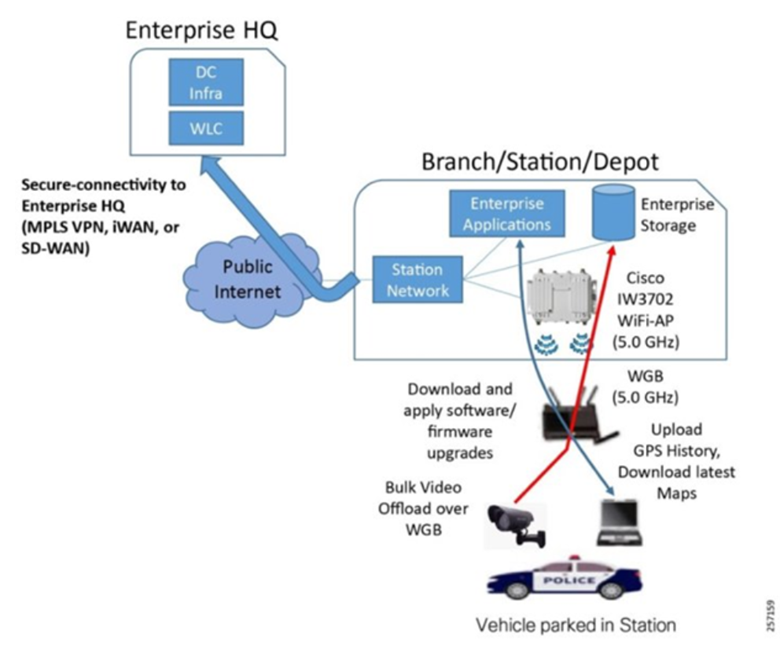
A workgroup bridge (WGB) is a mode that can be configured on a Wi-Fi access point to provide wireless connectivity to a wired client connected by Ethernet to the WGB access point. The WGB feature provides a high bandwidth uplink for the Mobile gateway when it is in range of the enterprise fixed wireless infrastructure. This allows for the secure and rapid transfer of bulk data without incurring Cellular bandwidth charges. WGB uplink is given a preference over cellular uplink when the Mobile asset is in the range of fixed enterprise wireless infrastructure.
The Cisco RaMA architecture supports branch station connectivity for local high bandwidth access for instances where cellular bandwidth utilization is cost prohibitive, such as uploading large files or downloading software updates. The Workgroup Bridge functionality provided in this solution allows the use of a Wi-Fi connection to offload such traffic and avoid cellular airtime costs. This provides a scalable Wi-Fi infrastructure to deliver secure and high bandwidth wireless connectivity to vehicles at the station to enable uploads of captured data, perform maintenance of devices in the vehicle, and downloads of configuration updates.
The Cisco RaMA solution supports this requirement via the following components:
- Cisco Wireless LAN Controller—A high-density controller for configuring and managing the APs, available in either a virtual or physical form factor.
- Cisco IW3702 Ruggedized Access Points—IP67-rated outdoor AP that provides IEEE 802.11ac Wave 1 Wi-Fi coverage for clients parked outside the station or in a parking garage.
- Station Network—This includes the branch router with backhaul connectivity to the enterprise headquarters (HQ) using any number of technology options such as MPLS VPN or iWAN/SD-WAN. It includes PoE-enabled switches to power the wireless APs and provide them with network connectivity.
Figure 2: Branch Station Architecture
Once the correct hardware is selected based on the network components, it is time to look at the network services available for robust WAN design. Following are the Network services available for the WAN:
Network Reliability
A reliable network is a priority when it is collecting and carrying important data from various network components like sensors, PLCs etc. To assure reliability, failover scenarios can be configured for the various supported WAN interfaces. These failover scenarios make sure that the data traffic is delivered successfully despite any bottleneck links in the network.
Failover options
Based on the customer requirement for various performance metrics like Packet loss, bandwidth, jitter and latency, failover scenarios can be determined and designed. If any of the performance metric reduces the network efficiency, in that case failover between interfaces (Gigabit Ethernet or Cellular) can be configured with the help of IP SLA and the routes can be switched using routing admin distance. Configuring failover links gives a high resiliency to the network.
Cellular Redundancy Options
Both IR800 and IR1101 support following failover options for cellular interfaces:
- Dual Radios Dual SIM: It provides the highest resiliency with two separate cellular radios each with their own SIM card.
- Single-Radio Dual-SIM—It provides resiliency by allowing the use of a backup service provider using a second SIM. But at once only one radio network can be used.
IP SLA
IP SLA (Internet protocol service level agreement) is a feature of Cisco Internetwork Operating System (Cisco IOS) that allows collection of information about network performance like response time, jitter, latency, and packet loss in real time. Primary use case for IP SLA is configuring failover links as a redundancy measure in the network infrastructure. IP SLA collects and monitors various performance metrics and if any of those violates the set threshold value then the route tracks are switched, and the entire traffic is redirected through a configured failover link keeping the connectivity constant. IP SLA can be configured in two parts. There is the IP SLA router, which generates the traffic, and the IP SLA Responder. IP SLA Responder is not required for IP SLA to function, but it does allow for more detailed information gathering and reporting.
Quality of Service (QoS)
Quality of Service is a technique that helps in managing network resources by managing various performance metrics like bandwidth, latency, and packet loss across the network. In RaMA solutions, if a customer needs traffic segmentation for different types of data traffic like application traffic, delay-sensitive traffic, or real-time traffic then this can be attained using QoS. Multiple tunnels can be provisioned from enterprise network, traffic forwarding to each of these tunnels will be based on the policies configured for that particular tunnel. This ensures that the bandwidth insensitive applications do not affect the bandwidth sensitive data or application in the network. QoS offers best set of techniques to manage network resources efficiently. It makes sure that the business-critical data gets transported over the network with efficient bandwidth and no delay.
Quality of service (QoS) consists of the following key components:
- Classification: It is the process of segmenting one type of traffic from another based upon Class of Service (CoS), type of application generating traffic, Access List Control (ACLs) and other factors.
- Queue: Queuing is used to overcome traffic congestion. Traffic is sent to a specific queue based on the bandwidth allocated, it is then scheduled and sent out when the there is a link availability.
- Marking and mutation: Marking is used on traffic to convey specific information to a downstream device in the network, or to carry information from one interface in a device to another. When traffic is marked, QoS operations on that traffic can be applied.
- Shaping and policing: Shaping is the process of imposing a maximum rate of traffic, while regulating the traffic rate in such a way that downstream devices are not subjected to congestion. Shaping in the most common form is used to limit the traffic sent from a physical or logical interface. Policing is used to impose a maximum rate on a traffic class. If the rate is exceeded, then a specific action is taken as soon as the event occurs.
Virtual Private Networks (VPN)
The RaMA solution provides a Management FlexVPN tunnel between Cisco Enterprise Network and each managed gateway. Additionally, an optional FlexVPN tunnel can be configured between the managed gateway and the customer-owned VPN headend. Both tunnels provide secure, encrypted data transport for management and data plane traffic.
For better resiliency with the Enterprise VPN headend, a customer can choose to provision multiple FlexVPN tunnels between managed gateway and the Enterprise Network. This will ensure failover for the management and data plane traffic.
For better security, if the customer wants to segregate the traffic based on various services or applications, multiple FlexVPN tunnels can be provisioned in conjugation to the relevant VRFs. This enhanced security ensures safety and redundancy via traffic monitoring and segmentation.
Routing with IKEv2
When utilizing the option to create a FlexVPN tunnel from the managed gateway to the enterprise VPN headend, the underlying Internet Key Exchange Protocol version 2 (IKEv2) protocol is able to advertise networks to the remote side (bidirectionally, from hub to spoke and spoke to hub). This functionality enables each spoke (managed gateway) to advertise unique networks to the enterprise via the headend, making the network behind the gateway directly reachable across the FlexVPN tunnel to the enterprise headend. This option can be somewhat more complicated to deploy, as each remote site (gateway) needs to be individually configured for its unique subnet.
However, this option gives enterprises granular control over which traffic from the remote gateways will traverse the enterprise headend network. If only some traffic needs to go to the enterprise, then a specific route can be advertised to the remote site, allowing all other traffic (the default route) to exit the gateway’s WAN interface directly. In more security focused networks, the headend router can advertise a default route to the remote gateway, ensuring that all traffic destined for the enterprise headend (except for IoT Operations Dashboard management traffic) traverses the FlexVPN tunnel. At the headend, comprehensive security applications and policies can be deployed to restrict, analyze, or monitor all remote site traffic.
For more information on load balancing techniques using IKEv2 refer to the Enterprise Network Integration Module.
Routing and WAN Interface Prioritization
Routing functionality on Cisco industrial routers and gateways establishes the logical connectivity between different local and remote networks. In a simple use case where a router only has one WAN connection, all that may be required is a single default route that will send traffic to all (non-local) destinations out that WAN interface. In more complex scenarios involving multiple WAN links, or virtual links (VPN tunnels for example), additional routing capabilities should be employed to provide the desired behavior. For example, additional static routes may be required to send traffic destined to a specific host or subnet out a specific interface (like the WiFi uplink, or a VPN tunnel to the enterprise data center).
In most RaMA use cases, the static routing, WAN interface prioritization, and IP SLA tracking features in the IoT Operations Dashboard eCVD templates can be used to define a policy whereby the router maintains internet connectivity with minimal downtime, even in the event of a upstream failure or a dynamic environment (like a moving vehicle).
In some circumstances, dynamic routing may be used to automatically learn and advertise route information. This may be needed in deployments where each router has a unique LAN subnet, and NAT is not being used, or in cases where network failure detection time needs to be minimized as much as possible.
Zone Based Firewall
Zone-Based Policy Firewall (ZFW) is a new configuration model for the Cisco IOS Firewall feature set. This new configuration model offers intuitive policies for multiple-interface routers, increased granularity of firewall policy application, and a default deny-all policy that prohibits traffic between firewall security zones until an explicit policy is applied to allow desirable traffic. In Configuring ZFW, Interfaces are assigned to zones, and inspection policy is applied to traffic moving between the zones.
For more information about Zone Based Firewall, refer to the RaMA Security Module
LAN Connectivity
For building LAN connectivity, following network components can be put to use: Wired LAN connection can be extended via Ethernet, Serial and General-Purpose IO ports and Wireless LAN connection can be supported via WiFi.
Wired LAN Options
Wired LAN connection can be established with Ethernet interfaces, serial interfaces and GPIO. Let’s look at each of these design components in the following section:
Ethernet Interface
In RaMA solutions, deployed gateways have varied number of Fast Ethernet and Gigabit Ethernet interfaces to extend the LAN connection at the remote site. IR829 supports four Gigabit Ethernet ports and IR1101 supports four Fast Ethernet ports for LAN connection. Power over Ethernet (PoE) is the ability for the LAN infrastructure to provide power over a copper Ethernet cable to an endpoint or powered device. Currently the PoE functionality is available on IR829M, IR829GW and IR829-2LTE models. It has 30W of PoE/PoE+ shared across the four Gigabit Ethernet interfaces.
Serial Interface
In RaMA solutions, the deployed remote gateways provide serial interface connection for extending LAN connectivity to the devices with serial ports. Serial interfaces are used to connect the industrial devices like sensors, controllers etc. to the gateway for transferring and monitoring the recorded data. Following are the serial ports available with the currently deployed gateways:
- RS232 (IR829 and IR1101)
- RS485 (IR829)
All these serial interfaces support Asynchronous mode.
The IR1101 expansion module IRM-1100-4A2T supports 4 additional Asynchronous RS232/RS485 serial ports.
Wireless LAN Options
Wireless LAN can be designed using the WiFi hotspot available on IR800. Once the antennas are attached to the radios, a valid SSID can be configured for authenticating the clients connecting to the WiFi network. The WiFi section explains the important network components and services that are required to configure WiFi:
Wi-Fi
Note: Wi-Fi hotspot is available only on the IR800 router. The IR807, IR809, and IR1101 routers do not support Wi-Fi. This section is focused on the capabilities of the IR1800 but some general concepts apply to other platforms. The IR1101 router does not support Wi-Fi.
The IR1800 router makes WiFi6 connectivity available for downstream client access. The ability to wirelessly connect laptops, phones, tablets, cameras, and a wide range of other devices to the mobile gateway enables clients to achieve an experience consistent with being within range of the enterprise wireless infrastructure or, if so desired, a public access point for internet access.
The IR1800's WiFi6 module (part number WP-WIFI6-X where X is the region code) can operate in one of three available modes: Controller Mode, EWC Mode, or WGB Mode.
Figure 3: IR1800 WiFi6 Deployment Scenarios
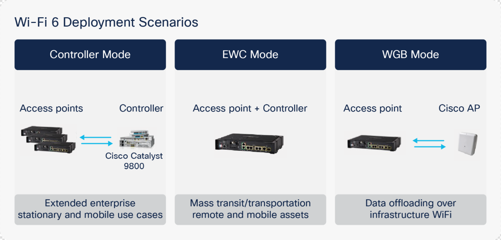
By default, the access point onboard the IR1800 operates in dual-band mode, utilizing both its 2.4 GHz and 5 GHz radios for client connections, providing maximum performance and compatibility.
A Service Set Identifier (SSID), which is generally used as a “name” to identify a wireless network, is used by client devices to specify which network they would like to join. Depending on the use case, it may be beneficial to use a unique SSID for each IR800 acting as a hotspot or use a common one across all APs deployed across an enterprise.
If the intent is for individuals to only have access to a single IR800's network, using a unique SSID and PSK for authentication may be ideal. This is available through EWC Mode since the wireless APs are not integrated with the corporate wireless infrastructure and the Cisco Wireless LAN controller. This mode would be ideal when no integration with the corporate WiFi infrastructure is required. This would be the case when providing free public WiFi to third-party users within city fleets (buses, taxis, etc.).
If the goal is to provide a unified extension of the fixed enterprise wireless network, Controller Mode allows for the use of the same SSID and authentication method that is used in the fixed wireless network. When using this mode, the gateways use a Cisco Wireless LAN controller for AP configuration and management. This is ideal for businesses with existing Cisco Unified wireless infrastructure and allows the existing fixed wireless infrastructure to be extended to the mobile gateways. This provides centralized configuration management and monitoring of the APs onboard the IR800. This also helps provide a seamless experience for employees connecting to the fixed wireless network by creating a wireless network “bubble” around the IR800 without needing to use a different SSID or authentication method.
Note: Unified Mode is not supported or configurable via the eCVD templates in IOT Operations Dashboard. If unified mode is desired, a new or modified template must be created. Configuration and management of the IR1800's WiFi module is not currently support in IoT-OD but will be available in a future release.
Authentication of wireless clients is accomplished by following methods:
Open
An open authentication is when the user needs no password to connect to the established WiFi network. There is no authentication for the users in the open mode.
Pre-Shared Key (PSK)
The simplest form of authentication is via a pre-shared key (PSK), which is essentially a common password that is shared by all clients that need to connect to the wireless hotspot network. A PSK is best suited to use cases where ease of connectivity is prioritized over security, such as in a public transportation vehicle where the goal is to provide hotspot connectivity for passengers. The PSK is communicated to users out-of-band (for example, by a posted sign or word-of-mouth).
Wi-Fi Protected Access-2
WPA2 requires a RADUS server to authenticate network users accessing the WiFi. Because each device is authenticated before it connects, a personal, encrypted tunnel is effectively created between the device and the network. WPA2 provides a very strong data protection and network access control because only authorized users can access the network.
WPA2 with 802.1x
Wi-Fi Protected Access version 2 can be used with RADUS server to authenticate network users accessing the WiFi. Because each device is authenticated before it connects, a personal, encrypted tunnel is effectively created between the device and the network. WPA2 provides a very strong data protection and network access control because only authorized users can access the network. IEEE 802.1x, is a standard mechanism for network-based authentication. 802.1x defines how Extensible Authentication Protocol (EAP) packets can be encapsulated for use over LANs (this is called EAPOL, for EAP over LAN), including wired Ethernet and wireless 802.11 networks. Three parties are involved in every 802.1x authentication transaction:
- Supplicant—This is the end client device, such as a laptop, phone, or tablet that needs to access the wireless network. Typically, the supplicant functionality is built into the operating system or could be implemented in another application such as Cisco AnyConnect.
- Authenticator—This is the network device, such as a wireless access point, or a switch that acts as an enforcement point in the network, blocking client access until authentication is complete.
- Authentication server—This is an application that authenticates the supplicant and typically communicates using protocols like RADIUS and EAP.
For clients to authenticate using 802.1x, the WAN connection from the IR800 to the RADIUS server must be available. If the WAN connection is interrupted, new wireless client authentications will fail, and clients will not be able to connect. Clients using PSK authentication is still able to authenticate locally on the AP if the WAN connection is interrupted.
Best Practices
WAN Connectivity
- Cisco recommends the use of FlexVPN if connectivity to the enterprise network is required.
- Using FlexVPN with VRF (options A and C) provides the most security for data plane traffic.
- When remote access to devices behind the router is important, using static IP addressing may be ideal.
For best coverage and performance with any wireless connection (Cellular, Wi-Fi, etc.), use the proper antenna based on the use case.
LAN Connectivity
- When using static IP addressing for LAN devices behind the managed gateway, only assign IP addresses that are within the address range of “excluded addresses” (configurable for custom subnets).
- It is recommended that if you use DHCP for initial address assignment, power up and/or connect the LAN devices in the order that you want the addresses to be assigned, as the addresses are assigned sequentially.
- Disable unused LAN ports, which helps prevent a malicious person or device from connecting a wired device to the gateway.