Overview
The RaMA solution takes advantage of the flexibility, security, and power of industry leading Cisco routers while simplifying deployment so that IT personnel are not needed to deploy hundreds to thousands of gateways. This module guides field operations staff on how to deploy these gateways using simple tools and without requiring knowledge of complex IT tools.
The RaMA solution leverages powerful management tools such as the Cisco IoT Operations Dashboard to apply IT and security policies to the gateway yet provides a simple and easy-to-use tool to deploy gateways in the field.
Requirements
Field deployment requirements for RaMA include:
- Support for all Cisco Industrialized gateways such as the IR807, IR809, IR829, and the IR1101
- Simple web-based tools to provision and deploy gateways
- Support the ability to download complex routing
- Support the ability to manage SIM cards including the abilities to:
- Enable and disable SIMs
- Set and modify rate plans
- Set and modify data limits
- Support for public and private Access Point Network (APN)
- Ability to monitor the health, status, and location of gateways
- Ability to track LTE/3G cellular usage
- Ability to do remote diagnostics on gateways to determine root cause of problems
- Ability to de-provision gateways so they can be used in future projects
- Ability to complete the provisioning process using a mobile phone without the need for a computer
Architecture
Figure 1 illustrates key aspect of the RaMA Field Deployment architecture.
Figure 1: RaMA Field Deployment Architecture
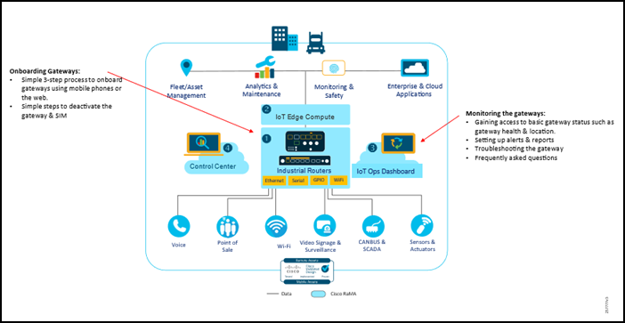
The Field Deployment architecture includes the following components:
- IR1101 Rugged Series
- IR1800 Rugged Series
The architecture leverages two cloud-based tools from Cisco, Control Center and Cisco IoT Operations Dashboard. All SIM and gateway management traffic is encrypted between the managed devices and the cloud-based tools.
Design
A key benefit of the RaMA solution is the simplicity of onboarding gateways, which allows non-IT users in the field to deploy the gateway with little to no IT support. This also significantly speeds up bulk gateway deployments across geographically dispersed locations. Leveraging IOT Operations Dashboard's template based configurations, office staff can define the desired feature set and fill in relevant details all at once allowing field technicians to focus on installing the hardware with without worrying about software configuration details. Once the devices are deployed in the field, monitoring and remote access capabilities help identify and resolve any issues that appear after installation.
It is recommended that prior to installing routers in the field, it is recommended to do a proof-of-concept deployment in a lab environment so that the desired configuration can be easily verified on a small number of devices before rolling out a large production network. Physical installation is just as important as the software configuration because it determines how the router stands up to the surrounding environmental conditions, as well as backhaul connectivity performance and reliability (especially in the case of cellular technologies).
For full details on how to prepare, configure, monitor, and remote access Internet of Things (IoT) gateways, refer to the Edge Device Manager (EDM) and Secure Equipment Access (SEA) sections of the IoT Operations Dashboard (IOT-OD) Documentation.
Troubleshooting details are covered in a separate section.
Installation Best Practices
In addition to the best practices described in this document, refer to the product installation guides below for official recommendations on mounting, power, antennas, and more.
Cisco Catalyst IR1101 Rugged Series Router Hardware Installation Guide: https://www.cisco.com/c/en/us/td/docs/routers/access/1101/b_IR1101HIG/b_IR1101HIG_chapter_01.html
Cisco Catalyst IR1800 Rugged Series Router Hardware Installation Guide: https://www.cisco.com/c/en/us/td/docs/routers/access/IR1800/hig/b-ir1800-hig/m-install.html
Cisco Industrial Routers and Industrial Wireless Access Points Antenna Guide: https://www.cisco.com/c/en/us/td/docs/routers/connectedgrid/antennas/installing-combined/b-cisco-industrial-routers-and-industrial-wireless-access-points-antenna-guide.html
General Consideratinos for Vehicle Installation
Before starting, plan the installation carefully so it will meet the following requirements:
- The installation must be safe for the operator and passengers within the vehicle.
- The installation allows for convenient access by the operator, as applicable (i.e., the Ethernet ports, console cable, sim cards, ability to view LEDs).
- The mobile radio is mounted in a location assuring the vehicle occupants' safety and out of the way of passengers and auto mechanics.
- The equipment is installed away from the airbag deployment areas.
- The equipment is protected from water damage.
- The installation is neat and allows easy service access.
Before starting the installation, it is imperative to determine the exact location in the vehicle where the equipment is to be installed. This action prevents hours of rework and reinstallation.
In addition to the considerations described in the previous paragraph, he mounting location for the router and any cables and antennas should account for the desired use case in terms of RF coverage for each radio and power source (battery or OBD-II).
Figure 2: Test Vehicle Installation- 1
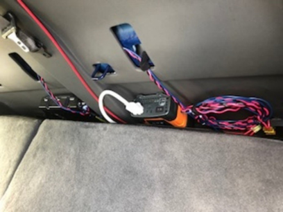
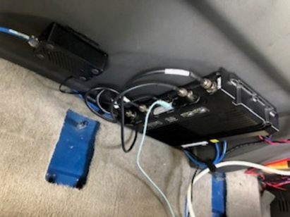
Figure 3: Test Vehicle Installation- 2
Special Consideratins for Vehicle Installation
Power Source Location and Considerations
- Some vehicles operate on 24 VDC, so it is important that the location chosen is a 12 VDC source. If a 12 VDC source is not available, a converter will need to be installed.
- Verify that the location chosen is a main power source and allows the addition of added terminals.
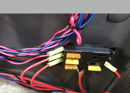
- If an auxiliary fuse block is to be used, check that the location chosen for the block guards against possible short circuits (see Figure 8).
Figure 4: Test Vehicle Power Distribution
Some vehicles, trucks, will have studs on the firewall that may be used to pass power without the need for a through hole. These can be used only if verified that they are not used to connect data cables or wires.
Ignition Sense Location and Considerations
- Chose an ignition sense that will not interfere with the safety-related systems of the vehicle.
- The ignition sense wire (white or blue wire) connection determines how or when power is applied to the mobile router. The white wire is sometimes referred to as the “white ignition switch wire”" or the “ignition sense input wire”. Regardless of the configuration, the router's main DC power input (red A+ wire) must be connected through an in-line fuse to unswitched vehicle DC power. The red wire must be connected to raw battery power (positive battery terminal) via the supplied fuse.
- It is important to use the proper crimp tool for crimping any terminals or fuse holder.
Power On/Off Using Vehicle Ignition
- The IR1800 can be powered directly by the OBD-II interface that provides a 12V (or 24V) power source in addition to the CANBUS interface. This installation allows for the use of the Ignition Sense feature to intelligently shutdown the router after a timer has expired when the detected input voltage drops, as is typically when the ignition turns off. Similarly, the router will turn on when the input voltage increases after ignition start.
- Alternatively, the IR1800 can be connected directly to the vehicle battery and leverage Ignition Power Management to turn the router off and on based on the voltage on digital input pin 5 which should be connected to the vehicle's ignition wire.
Ground and Return Location and Considerations
- Care should be taken to ensure the location chosen is truly to vehicle ground.
- The location chosen should not be in an area that is prone to moisture retention.
- Ensure that the location will protect the terminal from being bumped and allow the connection to loosen.
- The location must allow a through bolt with a nut and lock washer or be at a factory ground.
- Chose a location that will allow the ground lead to be as short as possible.
Antenna Mounting Considerations
- Antenna location must be chosen based on the installation instructions and in consideration of other items installed on the vehicle's roof.
- There must be at least a 24” separation between the antenna and any other roof mounted equipment (see Figure 5).
- If the antenna being used requires a ground plane, the location chosen must provide an acceptable ground.
Figure 5: Test Vehicle Antenna Placement

Data, Antenna, and Power Cable Routing Considerations
- Cables should not be routed under vehicle carpeting where the occupants' feet rest.
- Plan the cable runs to protect the cables from chafing, crushing, moisture, or overheating.
- Routing under the dash should not interfere with, or pass through, the steering column, brake pedal, clutch pedal, or the accelerator mechanisms.
- Carefully chose the location where the wiring will exit the passenger compartment and enter the engine compartment.
Splicing Requirements
Splicing the 12 VDC (A+) wire is not allowed. For other wires, if a splice must be installed such as to extend the wire, the following requirements must be followed:
- When wire is routed through hidden locations such as door jams, under the dash or, otherwise hidden from view use a solid run.
- Any splice installed must be visible to future service technicians. The best way to accomplish this is to cut off the wire back near the equipment connector and splice on a new wire.
- The splice wire used must have insulation rated for use in an engine compartment.
- Estimate the length of the run and determine required wire gauge.
- The gauge of the wire used must be based on the length of cable run for a load of approximately 5 Amps and maximum allowable voltage drop of 200 mV at peak load. If larger gauge wire is not required the same gauge shall be used, but never a smaller gauge.
- When splicing a wire that could be exposed to moisture use a butt splice encased within heat shrink tubing to seal the connection.
Battery Connection Requirements
- The 12 VDC power source should be the battery if possible. Other sources may be used if a battery connection is not available or feasible. Acceptable sources are the input to the main relay/fuse panel in the engine compartment, other main 12 VDC terminal, or installation of an auxiliary fuse block.
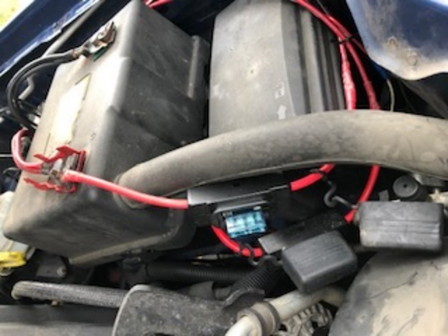
- An inline fuse holder is used for the mobile router to protect the equipment and the vehicle from a possible short circuit or excessive current draw. The fuse amperage must be according to the manufacturer's specifications. The fuse holder is water resistant to protect the fuse from the elements and avoid the possibility of corrosion. For optimum safety, the fuse should be placed as close to the battery as possible.
- If an auxiliary fuse block is being installed, the conductor used to connect it to 12 VDC should be gauged large enough to support the current flow of all the equipment that is fed by the block. The gauge of the cable to be used must be based on the length of cable run for a load of approximately 40 Amps and maximum allowable voltage drop of 200mV at peak load. In most cases this conductor consists of #6 AWG or #8 AWG wire. The insulation of this conductor must be properly rated for engine compartments. An inline fuse holder must be installed on this wire near the battery. The fuse holder must be water resistant and the amperage of the fuse installed should be rated large enough to handle the total current flow of the block. In most cases the fuse rating is 40 or 50 amps.
- The test vehicle utilized by AMK Services for this testing used a 60-amp fuse for the load which included a power inverter, a Raspberry Pi (Linux device), and multiple laptops at times. All needed equipment would need to be load rated and the fuse and wiring would need to be matched correctly to safely handle the load.
Figure 6: Test Vehicle Battery Connections
