Serial
Alert: Cisco has made the end-of-life (EOL) announcement for the Cisco Edge Device Manager (EDM).
This is a general overview of how serial ports work with the IR1101 device and the IRM-1100-4A2T expansion module. For more information on expansion module configuration, see Hardware. The serial interface allows you to configure serial ports to connect to a variety of devices such as security cameras and GPS devices.
Section and Field Descriptions
Note: Many of the input fields have the option to enter a value for a specific device, rather than a global value. This is helpful if there are multiple devices and some devices need specialized configurations.
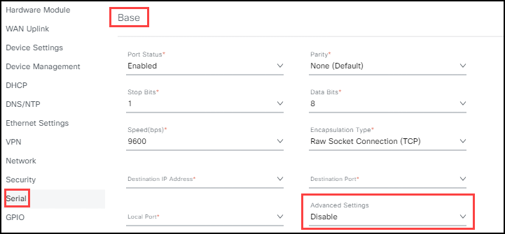
Base: If an expansion module is connected to the base, configure these settings:
- Serial # (1-4): Enable/Disable. Disable is the default setting.
Parity: Odd, Even, None. Default is None. Parity checks whether data has been corrupted while in transit to the receiving device. Select the type of communication checking process you are using.
Speed: Default is 9600 bps. Common baud rates to meet your network speed capacity.
Stop Bits: Default is 1. A drop-down list. Stop bit signals the end of a frame being transmitted over the connection. Select 0, 1, or 2 to meet your communication needs.
Data Bits: Default is 8. Data bits used to represent one character of data. Most data units requires eight bits. However, you may select 7 or 8 to meet your communication needs.
Encapulation Type: Raw Socket (for IPv4 and IPv6), TCP (for network messaging), UDP (time sensitive information used for streaming), and IOx. There are three types of encapsulation.
- Raw Socket Connection (TCP): An encapsulation mode that enables the serial client to establish a connection with a peer server. A raw socket client initiates TCP sessions with a peer server over an IR device and forwards packetized serial data to it. The peer server acts as a data collector to receive relevant information from the serial client. See Advanced Settings.
Note: The Serial Interface only supports client mode TCP encapsulation and not server mode TCP encapsulation.
Raw Socket Connection (UDP): An encapsulation mode that enables the serial client to establish a connection with a peer server. A raw socket client initiates UDP sessions with a peer server over an IR device and forwards packetized serial data to it. The peer server acts as a data collector to receive relevant information from the serial client. See Advanced Settings.
Relay-Line: An encapsulation mode that enables the communication between a serially connected device to the IR1101 and an upstream device. If the relay mode is IOx, then that serial device data is relayed to an IOx application. If the mode is reverse telnet, then the IR1101 device can connect to the serial device that enables console access.
Relay Mode: IOx and Reverse Telnet options. Select the mode that matches the conditions described in Relay-Line.
Destination IP: Default is blank. The IP Address to target the network host, for example, 1.2.3.4.
Destination Port: Default is blank. The IP Address port number for the network host, for example, port 1085.
Local Port: Port on the local IP address.
Special Characters: Lists any special characters that, when reached, triggers the device to "packetize" the accumulated data and send it to the Raw Socket peer. Examples are: CR, LF (line feed), or enter a Hex character such as 0x01-OxFE.
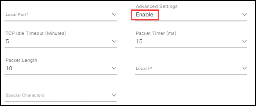
Advanced Settings (1-4): Enable/Disable. Disable is the default setting. Enabling Advanced Settings opens the following fields:
- Local IP: Local IP Address for the network.
- Packet Length (Range 2-1400 Bytes): Maximum number of received bytes of data before triggering the device to "packetize" the accumulated data and send it to the Raw Socket peer.
- TCP Idle Timeout (Default is 5 min. Range is 1-15 Minutes): Time interval (in minutes) where the communication channel times out if it is idle.
- Packet Timer (Default is 15 ms. Range 3 ms-1000 ms): Time the IR1101 device waits to receive the next character in a stream. If a character is not received by the time the packet timer expires, the data accumulated in the buffer is packetized and forwarded to the Raw Socket peer.
Configure serial port status for base or expansion modules to Cisco gear
Note: If the port status is enabled, all fields are required for the serial port to function correctly.
To configure each module serial port:
Select Enable for the Port Status and enter the settings required in steps 2-9. (Repeat steps 2-9 for each serial port utilized.)
Select the appropriate Parity setting for your device.
Select the appropriate Stop Bit setting for your device.
Select the appropriate Data Bits setting for your device.
Select the appropriate baud rate Speed.
Select the appropriate Encapsulation Type for your device Relay-line and Relay Mode to Reverse Telnet.
Enter the Destination IP Address for your device.
Enter the Destination Port for the IP Address.
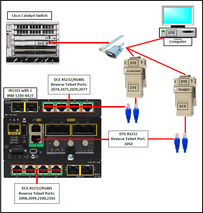
Enter the Local Port for your device. 2074-2077 for expansion module and 2050 for base.
(Optional) If you need to set specific information for a port, set Advanced Settings to Enabled and follow steps a-f.
a. Enter the Local IP address for the device.
b. Select the appropriate TCP Idle Timeout period in one minute increments from 1-15. The default setting is 5 minutes.
c. Enter the appropriate Packet Timer. Range 2-1400 in milliseconds.
d. Enter the Packet Length (2-1400 bytes). e. Enter the Local IP Address.
f. Enter any Special Characters that will trigger "packetization" and transfer of the data to the Raw Socket peer.
When finished with your serial port configuration, click Save. A success notice opens in the bottom right.
Serial port screen: Port Status Enabled and Advanced Settings Disabled

Serial port screen: Advanced Settings Enabled

Note: When configuring expansion modules, configure each port the same way as on the Base module.
Connecting IR1101 device serial port console to Cisco gear
- Set Encapsulation Type to Relay-line.
- Set the Relay Mode to Reverse Telnet.
- Set Media Type and Line Speed appropriate for your needs.
- Use the correct cable type based on the port type you are using. See diagram.
Note:
- For SEA, use Telnet as the Access Method with VirtualPortGroup0 IP and port shown in the image for its corresponding serial port.
- For IR1101, use Telnet
on the IR1101 CLI.
